What makes it work?
A home is a connected physical system. Heat, air, water, loads and occupants interact. Learn the mechanism before choosing a product or assigning a cause.
Explore how the parts of a home work together. These visual studies connect related systems; the guide library holds every complete article, organised by topic.
A home is a connected physical system. Heat, air, water, loads and occupants interact. Learn the mechanism before choosing a product or assigning a cause.
Observation, records and a new assessment answer different questions. A test has a location, date, purpose and limit. Missing information is an open question.
Climate, terrain, construction, shared ownership and local requirements affect the next step. Province or age alone cannot establish a property's condition.
These reading paths connect buyer questions with the owner lessons that explain the underlying systems. Read in order or follow the topic you need.
Understand the element, fins, room-air movement and thermostat. Then connect the actual equipment to comfort observations, electricity records and the questions a qualified provider should answer.
Follow water from the supply through a zone valve and buried pipe to the heads. Learn what the controller requests, what changing spray or wet ground can mean, and which records help a qualified provider assess it.
Learn what the paving, supporting layers and ground each do. Connect cracks, uneven areas and collected water with useful records, repair questions and the right assessment for the home.
Understand the switch, dimmer, LED electronics and power supply, then connect the actual products with electrical protection and renovation records.
Understand the appliance form, combustion routes, hot front and controls, then connect its records with the home’s wider safety and commissioning questions.
Follow water through a humidifier, learn how air gains or loses moisture, and keep a setting, an air reading and window water separate.
Understand the cooking surface and cavity, distinguish the fans and keep kitchen exhaust as its own documented route.
Follow dirt from the floor tool to the main unit, learn what the bag and filter do, and ask where the exhaust air goes.
Separate the storage system, present condition, retirement records and environmental scope. Provincial and municipal examples retain their geography and dates.
Identify the actual device, its building interfaces and service scope; assess the complete household route and actual local use separately.
Follow refrigerator heat removal, compartment air, controls and defrost water, then connect temperature history with outage planning and a new-home handover.
Understand an identified sprinkler mechanism, its supplied water and verification scope alongside household warning, shared systems and commissioning records. Local examples retain their Canadian jurisdiction limits.
Understand dishwasher washing, discharge and drying, then follow washer connections and the receiving supply, drain and leak questions.
Understand the floor finish, supporting construction and entry opening; connect a replacement proposal with sound, water, materials and handover questions.
Connect factory and site work with supporting ground, retaining walls, enclosure interfaces and completed systems.
Connect the shared-building documents with a particular assessment, technical work scope and remaining questions.
Read billing periods, separate operating and modelled evidence, and prepare a precise statement for a buyer or seller.
Connect the sewer system and camera scope with a reported repair, then understand how onsite wastewater records affect future use of a rural yard.
Follow equipment dependencies, flood-device scope and insurance questions; keep garage and crawlspace observations tied to the conditions actually seen.
Connect heating physics, installed-system records and room patterns with the limits of consumer air readings.
Follow deck support and wall interfaces, rural-water delivery and a sewer report back to the actual records that can answer your question.
Connect the wall, window, yard and foundation with indoor plumbing and water-service evidence. Separate what you can observe from what needs a qualified assessment.
Connect winter heat pumps, EV charging and backup loads with the electrical work and solar records a buyer should understand.
Read model-specific records, understand pressure and filter questions, and match new-build or property evidence to the appropriate assessment.
Read the inspection limits, plan dependent work and organize practical care with payments and retained cash kept separate.
Connect property form and system learning with the records and scoped assessment needed before deciding.
Connect the private source, indoor plumbing, onsite wastewater, land and operating record.
Start with the roof assembly, then connect winter conditions, cold surfaces, heat distribution and ventilation.
Connect site exposure with roofs, indoor air and water routes, then choose the evidence that fits this property.
Follow the visual new-build tour, deepen the system questions and assemble a useful handover and operating baseline.
Keep scheduled targets, active instructions, equipment response, ventilation maintenance and room measurements distinct.
Connect physical home questions with attributed repair history, inspection limits, applicable documents and each local project file’s actual status.
Read the statistic, compare relevant properties and keep construction findings and household commitments in their own evidence records.
Official regional resources are starting points. Conditions vary within every province and territory; a broad location is neither a hazard assessment nor a promise about a home.
All 13 regional starting points
Alberta’s groundwater portal links drilling, water-quality and pumping records for private-source questions.
Confirm whether this home uses a public supply, a well or another arrangement before choosing a water assessment.
A regional well record or climate label does not determine this property’s quality, supply or building condition.
PreparedBC’s hazard map is a starting point for questions about the surrounding area.
Ask what each hazard layer covers and how the actual site, elevation and building differ from the broad view.
Regional context does not establish soil conditions, ignition vulnerability or the performance of one enclosure.
Manitoba’s water-information portal provides forecasts, flood resources and river or lake context.
Mapped water conditions and drainage immediately around a foundation require different evidence.
A dry showing cannot reproduce seasonal water conditions or establish future performance.
The Water Security Agency’s domestic-use portal helps identify source-water questions and local resources.
A home’s actual water and wastewater arrangements matter more than a general rural label.
Neighbouring water results and regional descriptions do not certify this household’s source or capacity.
Ontario’s septic portal is a starting point for onsite wastewater identity and owner questions.
Municipal, private and shared service arrangements need confirmation at the actual address.
Ontario guidance should not be treated as a Canada-wide approval or inspection requirement.
Québec’s private-well portal links water-analysis and treatment starting points.
Use the actual local authority and qualified provider for the address and proposed work.
Linked resources may use different languages; this English guide does not claim complete bilingual regulatory coverage.
New Brunswick’s flood portal provides history and mapping resources for coastal and river questions within its coverage.
Read map scenarios and limits before relating them to a parcel or building.
The cause of a basement stain and actual insurance coverage need their own property-specific evidence.
Nova Scotia’s private-well portal links construction records, laboratories and water guidance.
Microbial testing, chemical testing and supply quantity are distinct questions.
A neighbour’s well or a clear-looking sample does not determine this home’s water condition.
The provincial drinking-water portal distinguishes public supply information from private-source testing resources.
Identify the actual supply and the appropriate local sample and interpretation route.
A province-wide service description cannot establish the source, equipment or exposure at a particular home.
PEI’s drinking-water testing portal separates bacteria and chemistry and identifies provincial laboratory resources.
Confirm the actual source and sample conditions rather than assuming one result covers every outlet.
A provincial testing program is a resource, not a property-specific guarantee or a universal transaction rule.
Yukon’s water-testing portal explains local sampling and laboratory starting points.
Ask about transport, access and the source conditions relevant to the actual test.
Territorial context does not establish that a site has permafrost or that a specific foundation strategy is suitable.
The territorial homeowner guide explains permafrost-related support and site-management questions.
Confirm the actual ground and foundation arrangement; do not infer frozen-ground reliance from the address alone.
A reported adjustment or site change needs its own dated scope and qualified interpretation.
Nunavut’s Climate Change Secretariat links climate-learning and permafrost-data resources.
Community context, the actual site and the installed building/service arrangement are separate scales of evidence.
A territorial resource or map cannot certify foundation support, service condition or suitability for one project.
The library is written in English and continues to grow. These resources do not replace municipality-specific records, current local requirements or an agreed professional assessment.
Find six official starting points for permits, inspections, property history, flood maps, warranty and winter-water questions.
Open the Calgary evidence hub ↗108 conceptual picture studies connect the words to physical relationships. Each is a conceptual teaching illustration, with limits made visible.
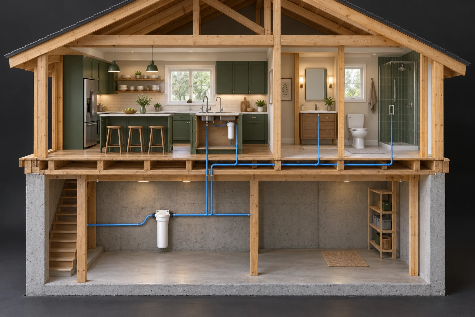
A device near the water entry can serve the downstream household supply. A point-of-use device treats water at a particular outlet, such as a dedicated drinking-water tap. These two locations answer different questions: what water reaches the home, and what water reaches the outlet you use for drinking. Identify the actual routes before comparing products or interpreting a sample.
The drawn branches are simplified; all valves, outlets, hot-water production and connections are not shown. The generic housings identify no treatment claim, approved installation or actual water quality.
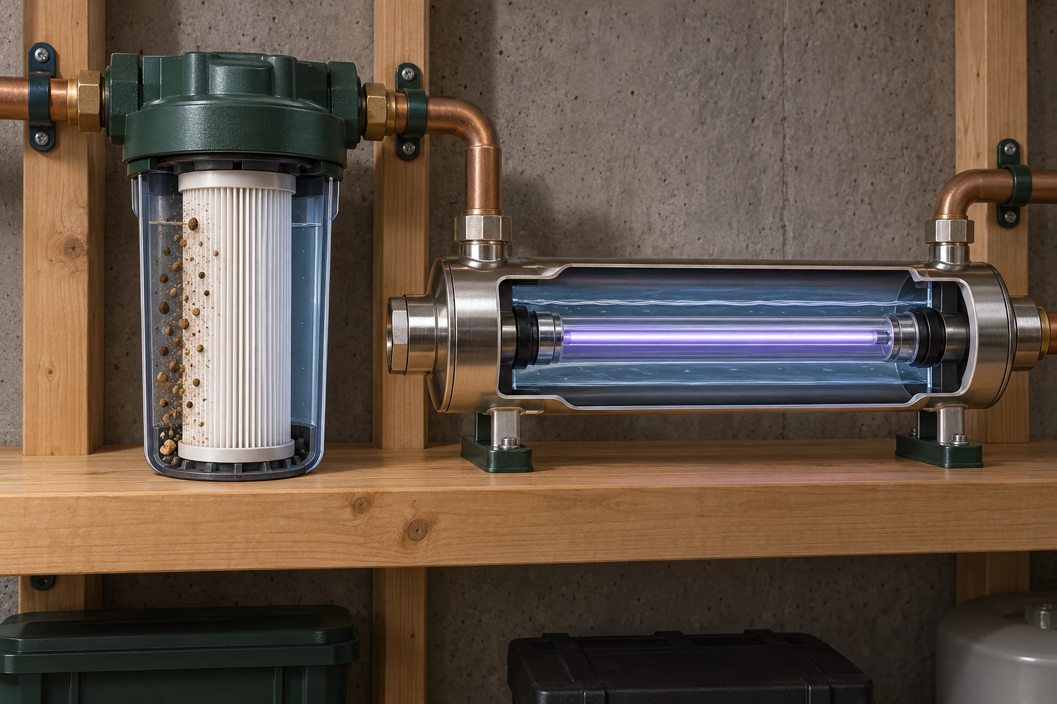
A cartridge filter can retain particles as water passes through its media. A UV unit uses light to inactivate microbes in water passing the chamber. Suitable water conditions matter to that process, which is why a treatment plan may include preparation before UV. A cleaner-looking cartridge outlet and an illuminated lamp answer different questions from a verified microbial treatment result.
The violet light is an illustrative tint, not a visible indicator of effective UV treatment. No flow direction, UV dose, controller, complete sleeve design, performance rating or service procedure is established. The drawn components are generic.
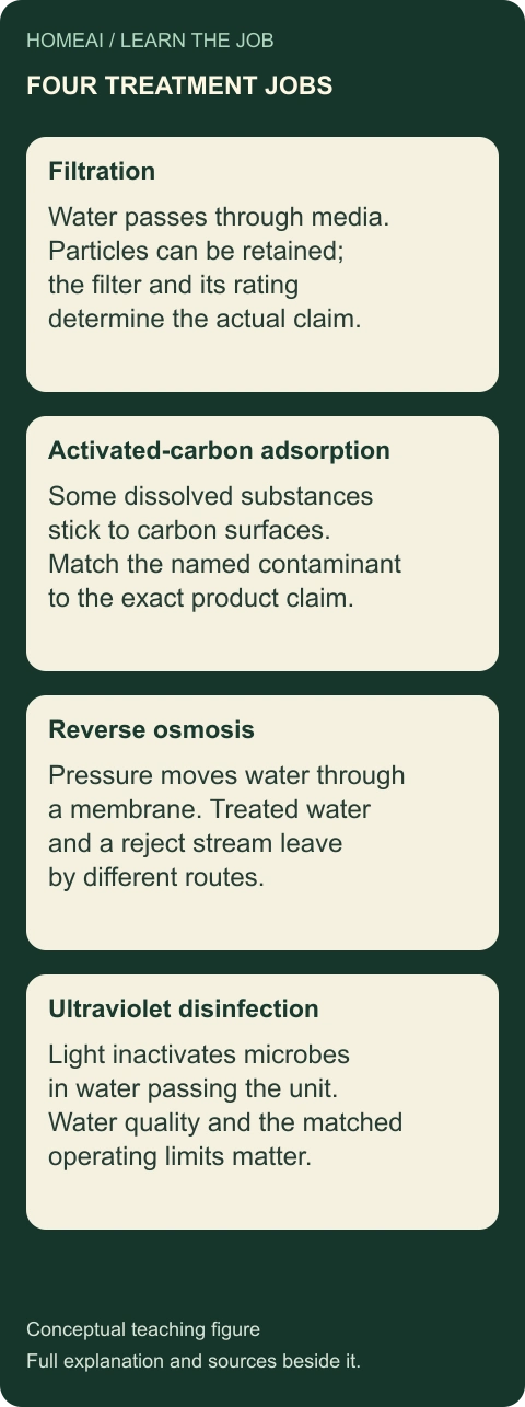
Filtration retains particles in media. Activated carbon can adsorb certain dissolved substances, meaning they stick to its surfaces. Reverse osmosis uses a membrane and separates treated water from a reject stream. UV uses light for microbial disinfection. Choose by the identified water concern and the exact verified product claim, rather than by calling every device a purifier.
These mechanisms are a comparison, not a recommended treatment train. No device rating, contaminant removal percentage, UV class, installation or approval is specified.
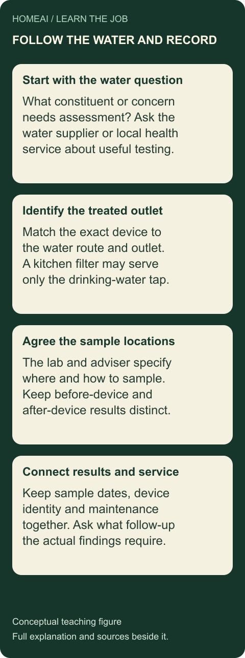
A result becomes useful when you know where the sample came from and which device was operating on that route. Start with the water concern, identify the treated outlet, agree the sample locations with the laboratory or adviser, then keep results beside the device and service history. This makes a before-and-after comparison understandable without pretending that one sample describes every outlet or future condition.
This is a record sequence, not a sampling procedure, universal testing interval or actual treatment result. Follow the laboratory and local health instructions for the circumstances.
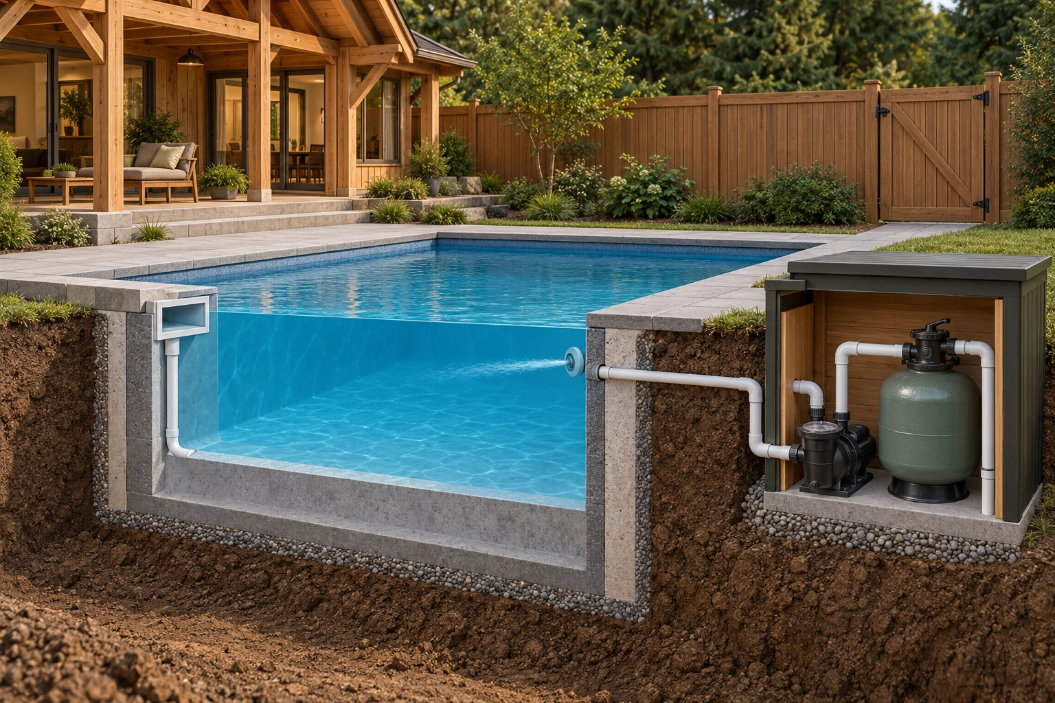
The pool shell contains the water. The pump moves water through the connected equipment, and the filter retains particles. The fence and gate concern access to the pool rather than water treatment. A buyer should therefore ask separate questions about circulation, water quality, access protection and the structure beneath and around the water.
The complete collection and return loop is not drawn clearly; use the labelled circulation lesson for those jobs. The image establishes no suction design, flow, disinfection, barrier compliance, shell condition or approved site detail.
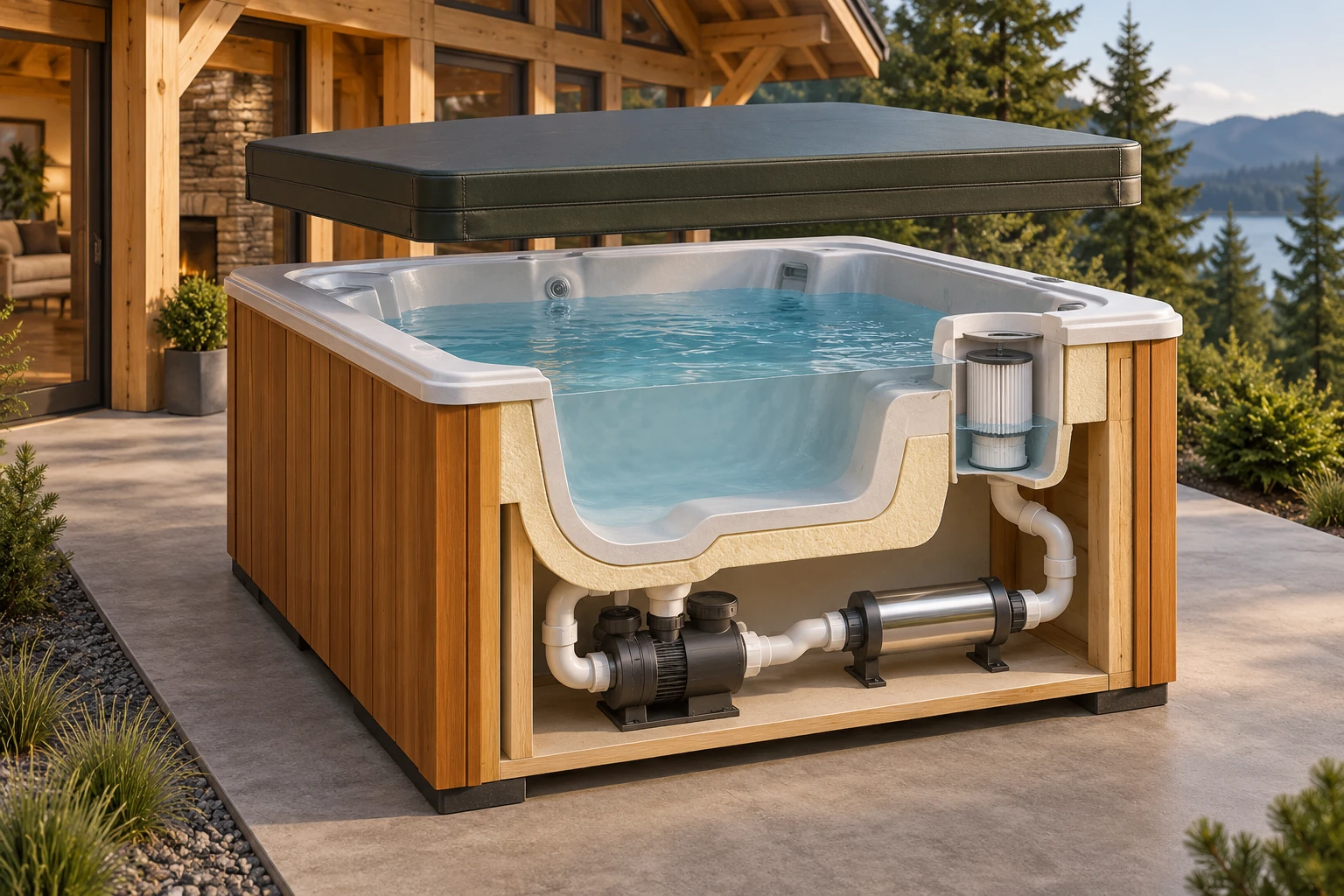
A hot tub combines a containing shell with circulation, filtration and heating. The pump moves water, the filter retains particles, and the heater adds heat. Those jobs do not replace disinfection or access protection. The cover is another part to identify at handover, with its own instructions and suitability questions.
This generic cutaway omits complete jets, circulation routes, controls and electrical connections. It gives no heating output, temperature, sanitation result, cover certification, support design or installation procedure.
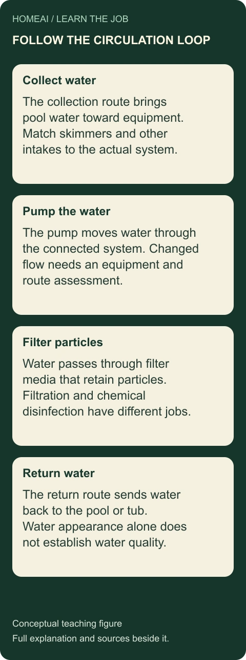
Collection, pumping, filtration and return work together. Water reaches the equipment through the collection route, the pump moves it through the connected system, the filter retains particles and the return route carries it back. Changed flow can involve more than one component. Circulation and filtration still need a separate water-treatment and quality plan.
This conceptual sequence gives no suction design, flow rate, drain arrangement, installation detail or troubleshooting procedure. Actual pool and hot-tub layouts differ.
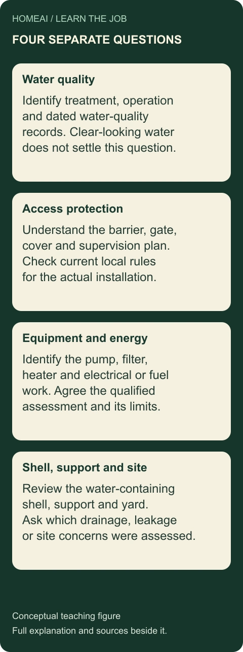
A water-quality record, an access-protection review, an equipment assessment and a shell or site finding answer different questions. Keep them together in the buying decision, while retaining each provider’s actual scope. This prevents a reassuring service invoice from becoming a claim about every part of the installation.
No actual assessment, jurisdiction-wide code rule, condition finding, repair approval or insurance decision is supplied. Requirements depend on the installation and location.
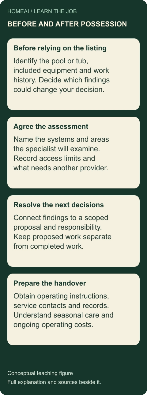
Begin with the identified installation and its work history. Agree appropriate assessments before relying on the feature, connect findings to any proposed work, then obtain the operating information needed at possession. Ongoing maintenance and seasonal care belong in the budget alongside any initial repair proposal.
This is a conceptual decision sequence, not a real inspection result, contractor quote, legal opinion or operating procedure.
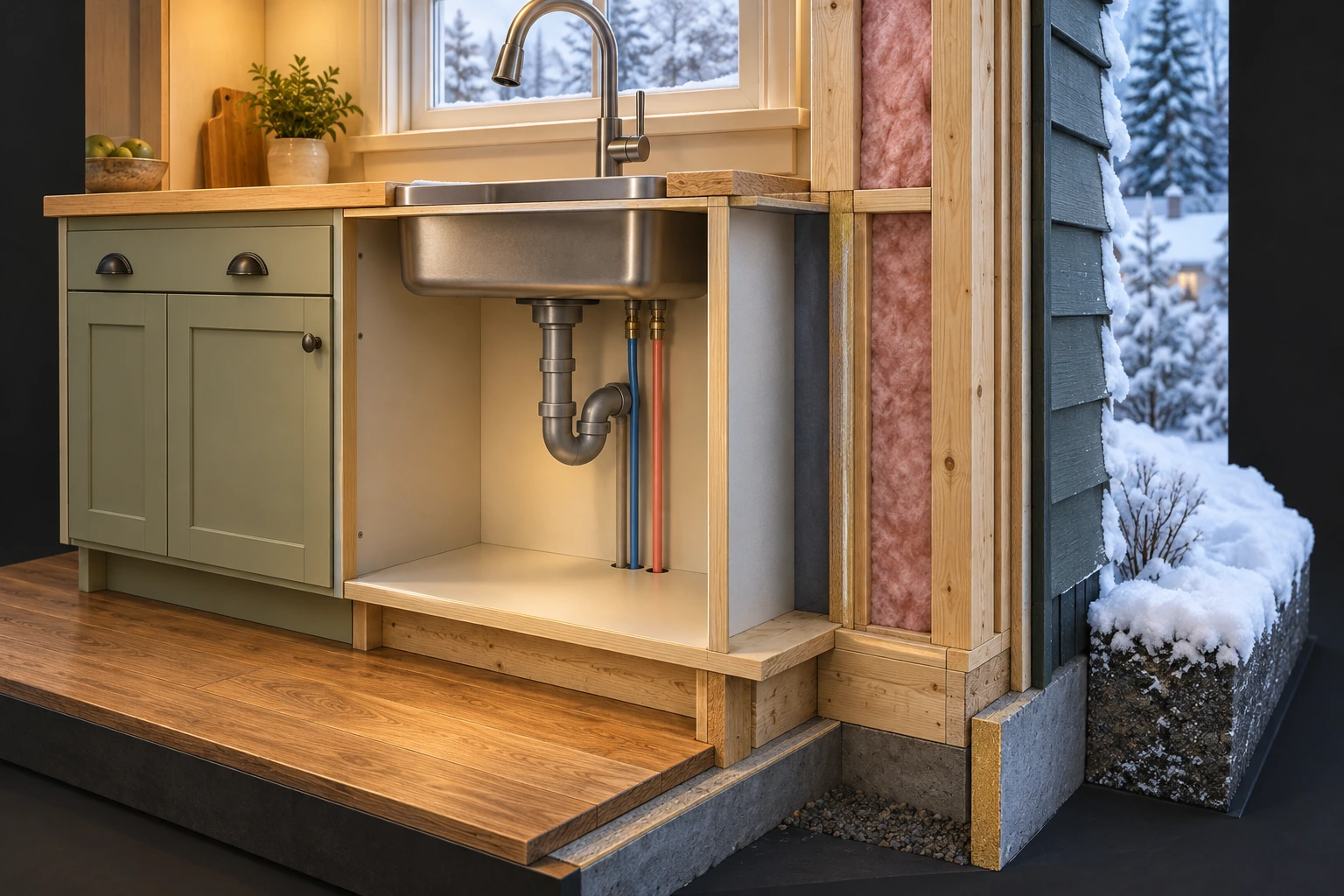
The slender supplies bring water to the tap; the larger curved drain carries used water away. Here the supplies sit at the back of a cabinet beside an outside wall. That location explains why the pipe can experience different conditions from the open room and its thermostat.
The front is removed to teach the parts. No actual pipe or room temperature, air movement, freezing, material identity, complete connection or approved wall assembly is shown. Blue and coral are teaching colours, not measured temperatures.
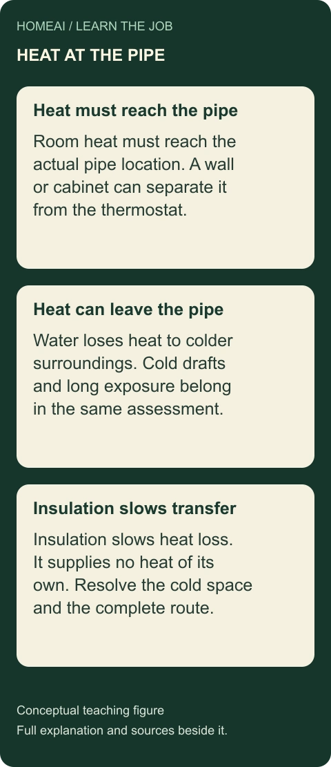
Winter protection depends on heat arriving at the pipe as well as heat leaving it. Insulation slows transfer; it cannot replace missing space heat or resolve every cold draft. Follow the entire vulnerable branch when comparing a proposal.
These are qualitative heat relationships. No temperature threshold, heat rate, freeze time, insulation specification or product suitability is supplied.
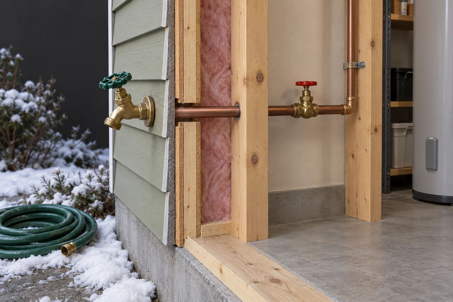
The outdoor tap provides water outside; the indoor branch supplies it. The separate valve illustrates why seasonal preparation must identify the correct branch and equipment. Municipal advice includes disconnecting hoses, while the actual tap and system instructions determine the rest of the preparation.
The picture gives no frost-resistant valve mechanism, drainage slope, confirmed valve position, complete winterization sequence or approval. The shown relationship is conceptual; do not use it to choose or operate an unidentified valve.
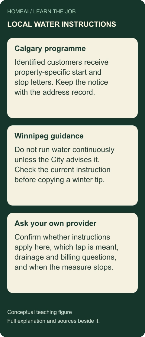
A utility may direct continued flow for an identified service problem. It brings supplied water through the route serving that fixture, not every branch in the house. Calgary’s property letters and Winnipeg’s general advice show why the address and current provider instruction matter.
Municipal examples were read October9,2026. They give no programme eligibility, stream size, bill credit or protection guarantee for another address. Toronto discusses its own optional measure and charges in the linked primary guidance.
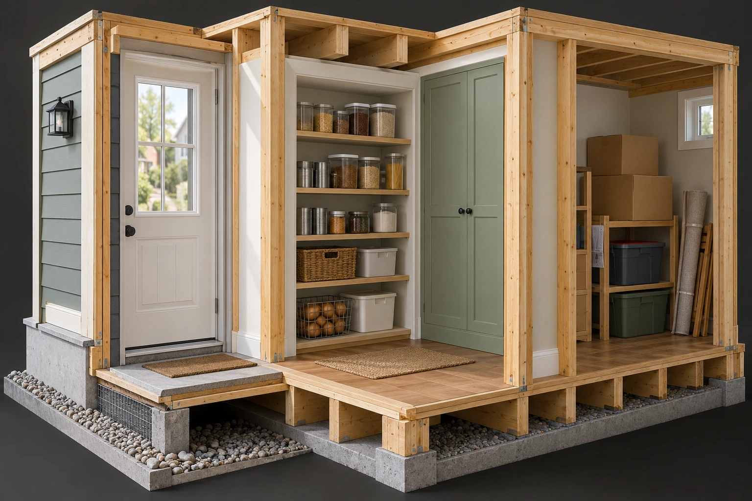
A rodent needs a way into or through the building and access to resources once there. The door, food shelf and storage nook give three familiar places to discuss. Notice that a tidy pantry can contain both closed jars and exposed food; appearance alone does not settle food access.
No animal, waste, nest, active route, infestation, contamination or repair result is shown. This is a comparison of locations and storage conditions, not a recommended pantry layout or pest identification.
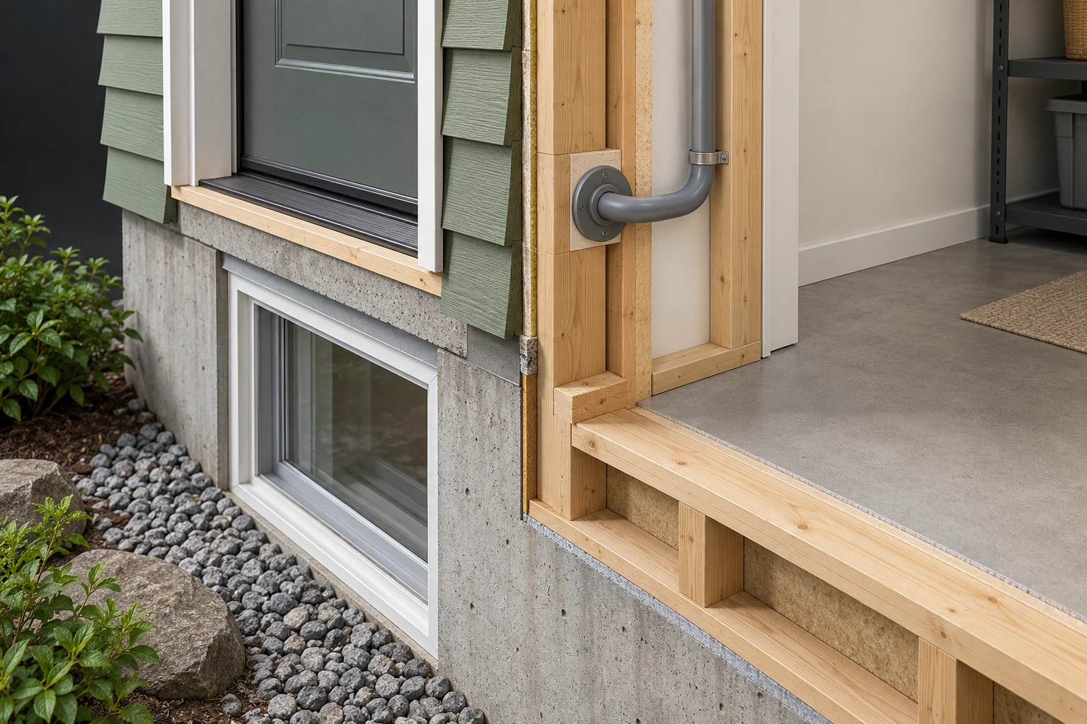
A door, window and service crossing interrupt the wall in different ways. An entry investigation asks which actual junction matters and what its building function requires. It should identify the problem before choosing exclusion work—the work intended to keep pests out.
The illustration establishes no opening size, animal passage, defective seal, pest identity or suitable repair. It does not depict a vent to close, authorize opening equipment, or supply a sealing detail.
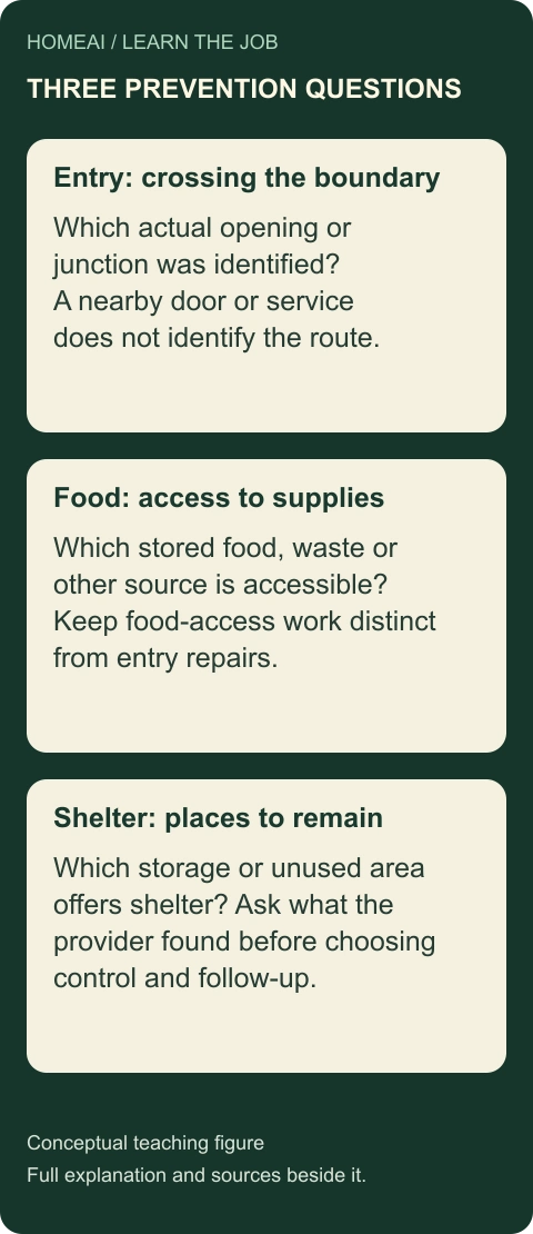
Entry, food and shelter can persist independently. Control directed at an identified pest and work on the building or stored resources therefore answer different questions. Ask the provider to connect each proposed task to an actual finding and a follow-up plan.
The cards are separate prevention questions, not a measured route or confirmed infestation. They give no pesticide, trapping or construction procedure.
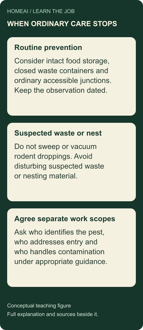
Routine prevention concerns intact storage and ordinary accessible building conditions. Suspected droppings or nesting material need a different response: do not sweep or vacuum droppings or disturb suspected nesting material. Obtain the appropriate contamination and cleaning scope rather than disturbing the material to identify it.
No disease risk at an actual property, clinical diagnosis, disinfectant, protective-equipment selection or cleaning procedure is supplied. Read current PHAC guidance and obtain suitable professional advice for the circumstances.
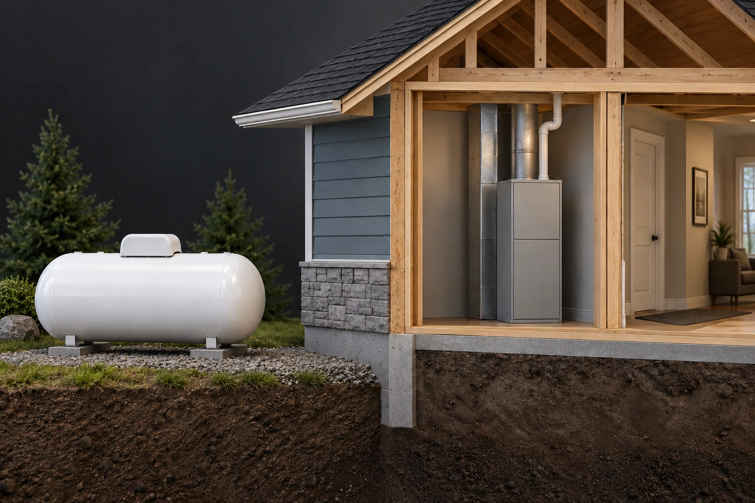
The outdoor tank stores propane. The furnace uses supplied fuel to produce heat, then its air system delivers that heat into the home. A buyer needs to understand both the fuel supply and the appliance; a record for one does not describe the other.
The supply route, regulator and operating connections are omitted. This is not an installation layout, approved separation, equipment selection or proof that this furnace is connected to this tank. Those functions are explained in the labelled comparison and actual property records.
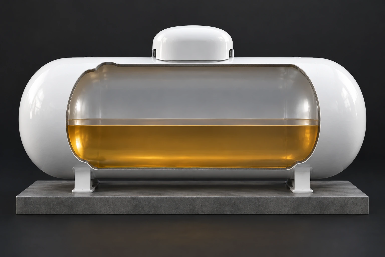
Propane can be stored as liquid under pressure while vapour occupies the space above it. In a household vapour-supply arrangement, the stored fuel and supplied gas are two parts of the same system. This is why a tank-level indication and gas-supply pressure answer different questions.
Amber is an illustrative colour, not propane’s actual colour. The arbitrary liquid level is not a permitted fill fraction or measurement. No vessel design, capacity, temperature, pressure, vaporization rate or valve arrangement is specified.
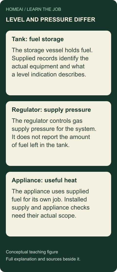
The regulator controls gas-supply pressure for the installed system. A tank-level indication concerns stored fuel. Neither is a substitute for the appliance’s own operating and service findings. Keeping those jobs separate makes a handover explanation easier to understand.
The cards give no regulator stages, pressure settings, sizing, fuel quantity, installation sequence or adjustment instruction. The responsible provider must identify the actual equipment and scope.
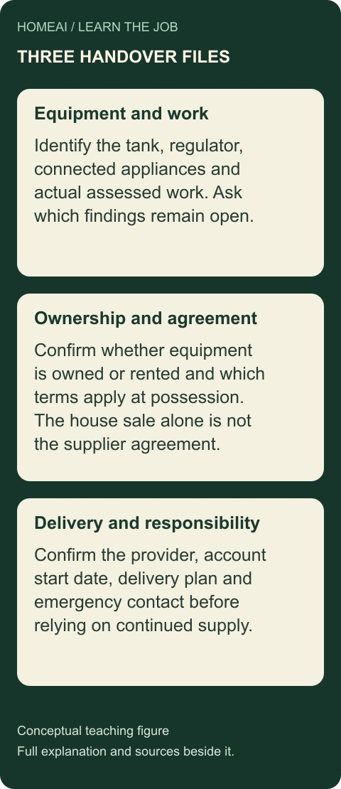
A buyer needs a technical equipment file, clear ownership or rental terms, and a delivery/account arrangement that begins at the right time. These tasks support each other, but they do not answer the same question. Resolve them with the supplier and transaction advisers before relying on continued service.
No contract transfer, legal opinion, actual condition, inspection result, price or assured delivery is supplied. Agreements and regulatory requirements depend on the provider, equipment, province and property.
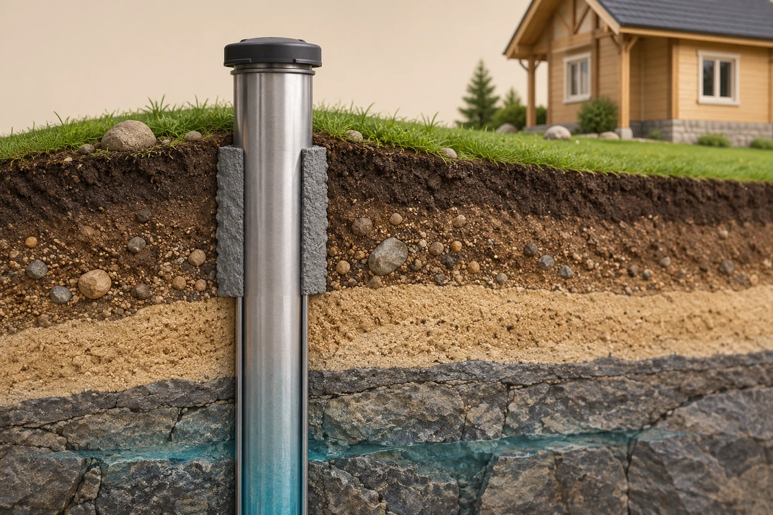
A closed cap and casing stand above grass. The virtual soil section exposes grey strips beside the casing and a teal band lower in the rock. A house sits in the background.
The grey strips introduce a concealed-seal question without authenticating an annular seal, its material or integrity. Teal colouring establishes no groundwater direction, contamination or sample result. Actual construction, buried condition, surface drainage, local requirements and appropriate separation remain unknown. The section is an illustration, not an opened well, installation detail or setback plan.
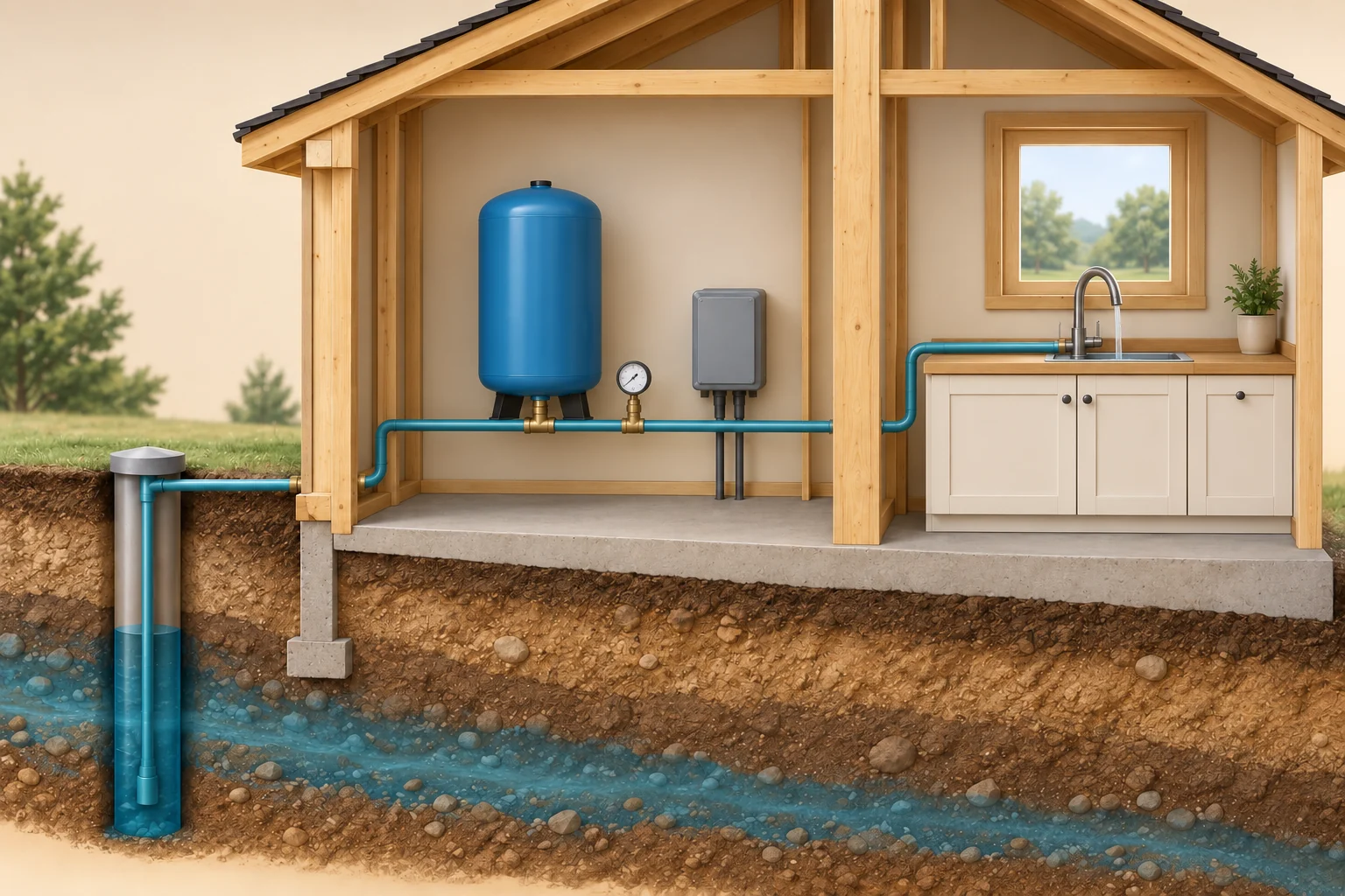
The teal main route crosses the room from the left well section toward the kitchen fixture. A short branch rises from that route into the base of a closed blue tank. A dial-like face and closed grey enclosure sit nearby. The house and ground are virtual cutaways.
The apparent route is a teaching simplification, not a verified pressure-piping installation or actual pump connection. No model, fuel or energy state, measured pressure, seasonal yield, usable tank storage, groundwater flow, water quality or treatment performance is established. The gauge supplies no usable reading. Keep real covers closed and do not operate or adjust equipment to reproduce the scene.
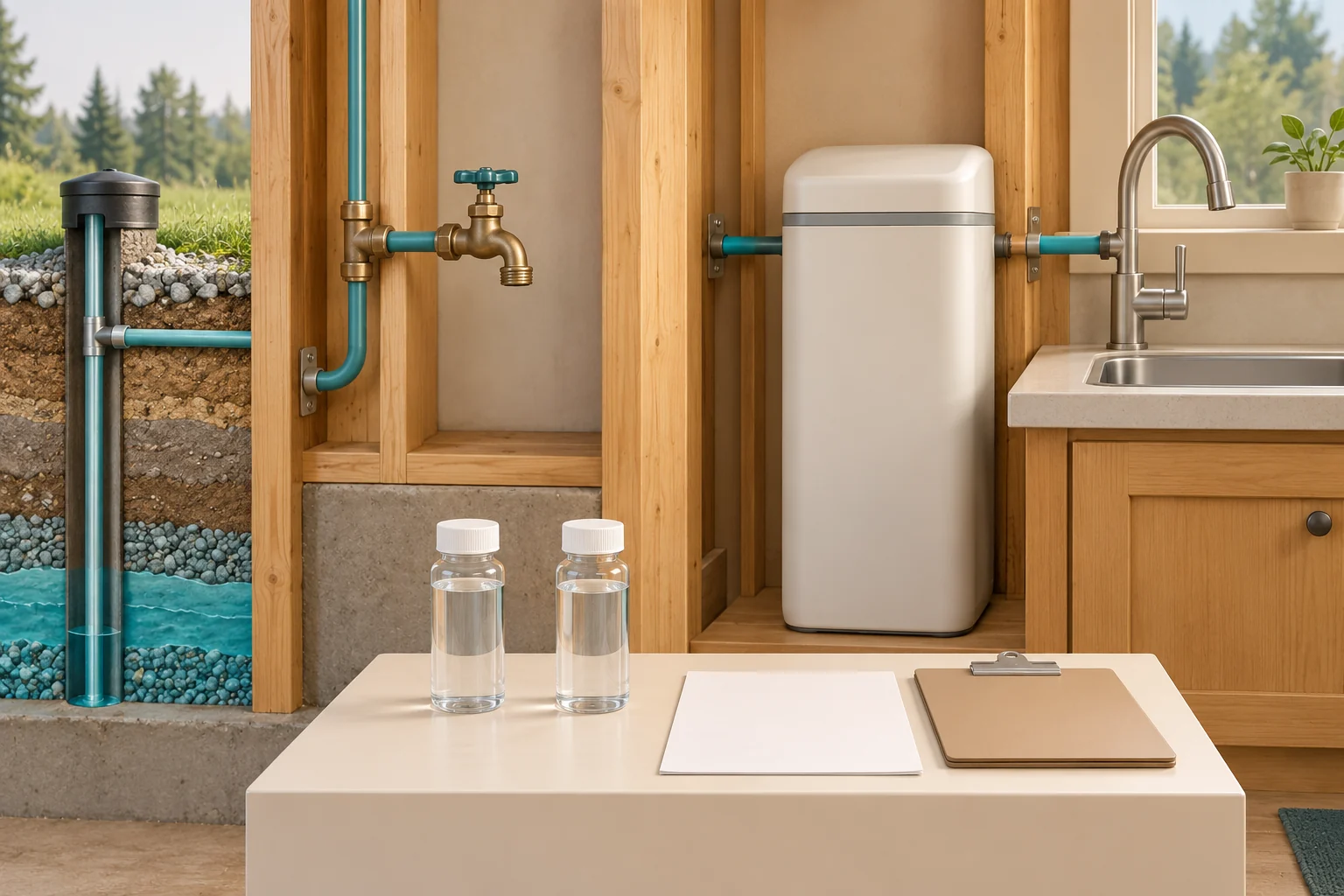
A left faucet and a kitchen faucet sit at different illustrated locations around an unnamed closed cream cabinet. Two capped clear bottles, a blank sheet and a blank clipboard lie separately in front. A virtual well section appears at left.
No bottle has an authenticated collection point, panel, result or handling history. The cabinet does not identify actual treatment, and its illustrated position cannot establish raw or treated water at either faucet. Blank pages supply no date, method, analytes, concentrations or drinking-water clearance. These are location and record questions, not approved sampling instructions.
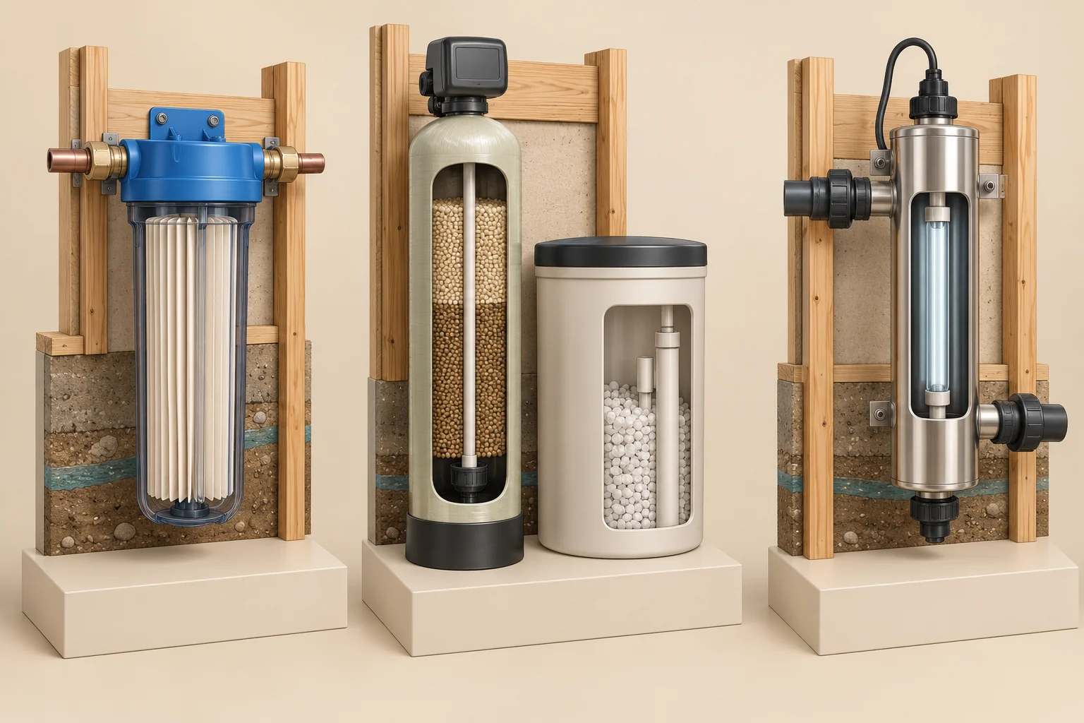
Three separate display stands expose a pleated cartridge, bead and pellet forms in paired vessels, and a tube-and-sleeve form inside a metal cylinder. Control faces and electrical connections remain closed. These interiors are virtual cutaways.
The forms introduce filter, softener and ultraviolet treatment questions without authenticating a product, certified target, installed sequence, operating condition or successful treatment. There is no connected treatment train or blank record in this picture. No contaminant, removal result, disinfection result or approved installation is shown. Do not open real housings, expose a lamp or change valves to reproduce the display.
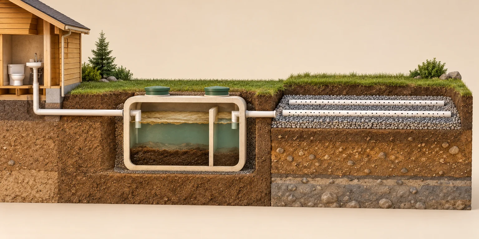
A house route reaches a sectioned tank with upper, middle and lower layers beneath closed green covers. A downstream display shows perforated-looking pipes in gravel above soil. The broad section is a fictional teaching layout.
The layers illustrate separation rather than measured contents or condition. No actual tank volume, pipe grade, working distribution, trench depth, soil profile, groundwater level, effluent quality, design approval or treatment performance is established. This conventional concept does not identify every Canadian arrangement. The virtual section is not permission to uncover, open or enter a real system.
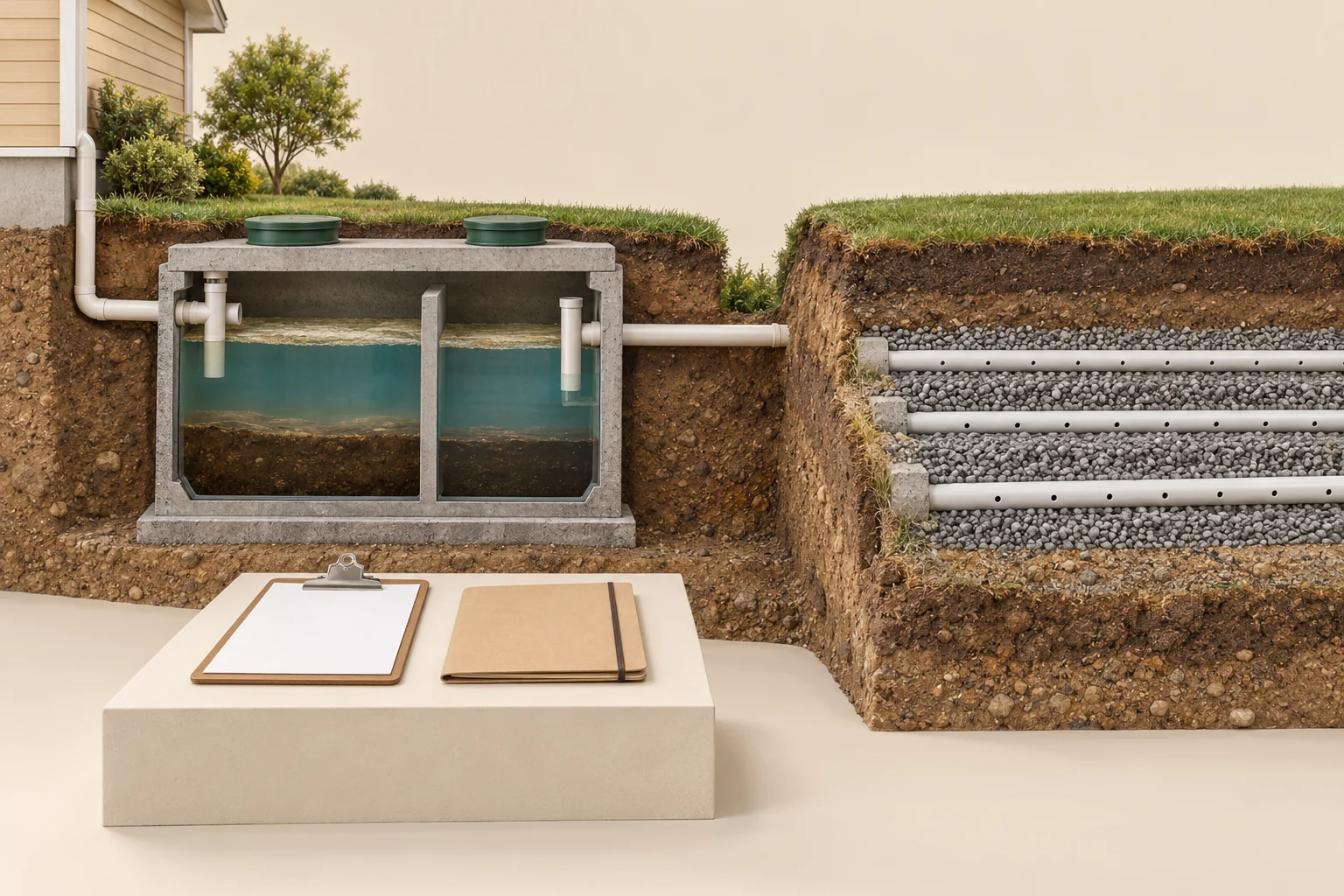
The tank section displays layers below closed green covers. Its outlet stops beside a gap separating the downstream pipe-and-gravel display. A blank clipboard and closed blank booklet sit in front.
The gap separates virtual display sections; it is not a depicted disconnected or damaged real pipe. No service has occurred and the blank paperwork proves no pumping, inspected reach, certification, removed quantity, condition, maintenance interval or assessed treatment-area performance. The cutaway is an illustration, not an access method or installation design.
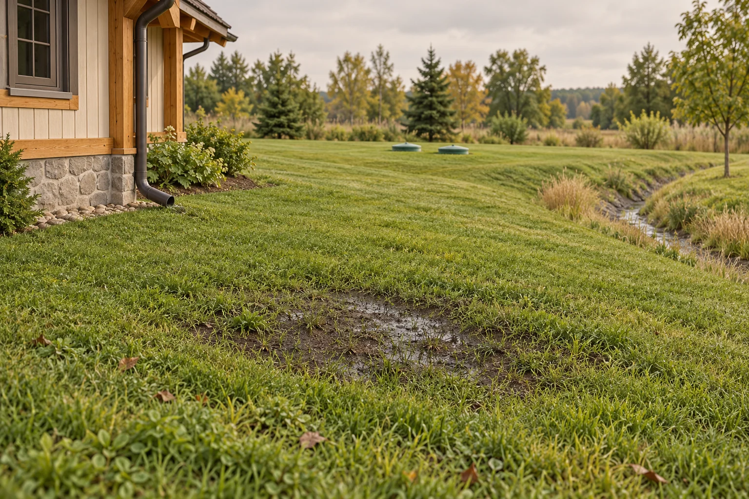
A wet-looking patch interrupts the foreground grass. A house downspout, two closed green covers and a shallow swale-like depression give separate surface landmarks. No buried route is exposed.
The scene identifies no sewage, actual connection, failed component, contamination, cause or safe contact. The downspout and depression are possible context rather than proven sources. Weather, occupancy, service history and qualified findings remain separate evidence. Do not touch or probe the patch, open covers, dig or stage a load test; keep people clear of actual contamination or insecure openings.
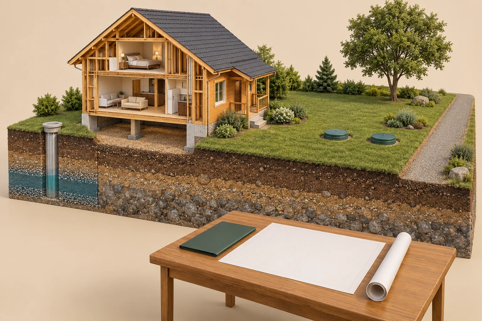
The house and ground are virtual sections. A well-casing specimen appears at left; two green covers remain closed in the lawn. A right-hand gravel path and blank paper specimens sit apart from these service landmarks. No hidden wastewater pipe is visible.
The layout supplies no actual locate, wastewater route, treatment-area extent, legal boundary, sharing right, access permission, reserve area, safe vehicle access, suitable addition or national separation distance. The well section reveals no actual construction or water result, and the blank sheet is no survey or as-built record. This is a site-question illustration, not an approved plan.
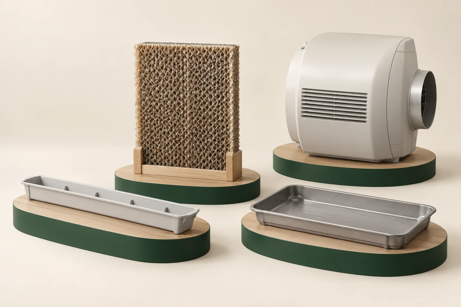
Four independent display specimens are separated on their own plinths. An elongated shallow trough sits at front left, a honeycomb-textured rectangular pad stands upright behind it, an empty shallow pan sits at front right, and a rounded cabinet with closed covers and a visible circular side port stands behind. No specimen is shown connected to another.
The picture identifies no actual model, material, installed seating, correct assembly, water supply or drainage connection, wetness, evaporation rate, mineral build-up, mould, fan status or safe servicing access. Pad texture and colour are not an inspected condition. The cabinet port establishes no connected route or airflow. This is a component-role study, not an exploded instruction to remove or arrange real parts.
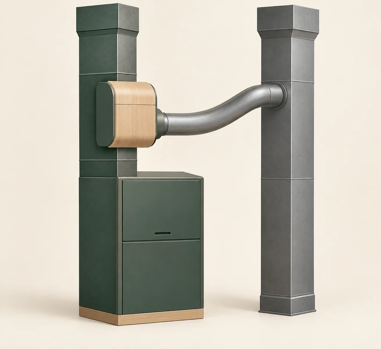
Two tall duct-like forms are visible. A rounded closed box appears on the left form above a closed green cabinet. A curved closed branch extends between that box and the right form. No arrow, water route, fan, reading or moving air is depicted.
Actual supply/return roles, complete household circulation, branch connection details, flow direction or quantity, heat source, model, fan/control coordination, water/drain paths, capacity and installation approval remain unknown. Green, wood-like and metallic finishes identify no operating function. The simplified geometry is a learning model, not a buildable arrangement or permission to attach or adjust anything.
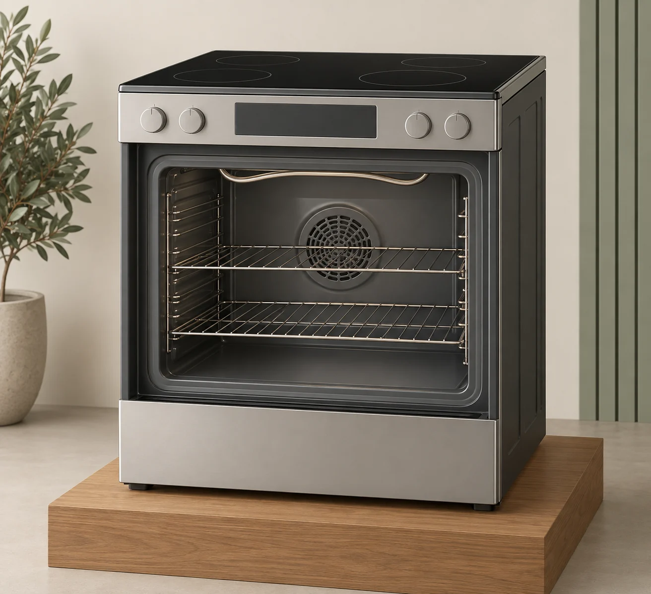
The front-cutaway cavity contains two empty racks, side rack supports, a curved upper metal form and a circular grille at the rear. The lower cavity floor is covered and shows no exposed lower element. Four circle outlines appear on the dark cooktop; the fascia display is blank. There is no food, flame, glowing part or operating reading.
No exact product, radiant or induction identity, energized state, heat-source output, temperature, hidden lower element, fan behind the grille, airflow, calibration, rack suitability, cooking result, installation or safe service access is established. The open front is a display cutaway rather than an instruction to remove a door or reach inside. Cooktop circles and metallic forms do not establish an operating mechanism.
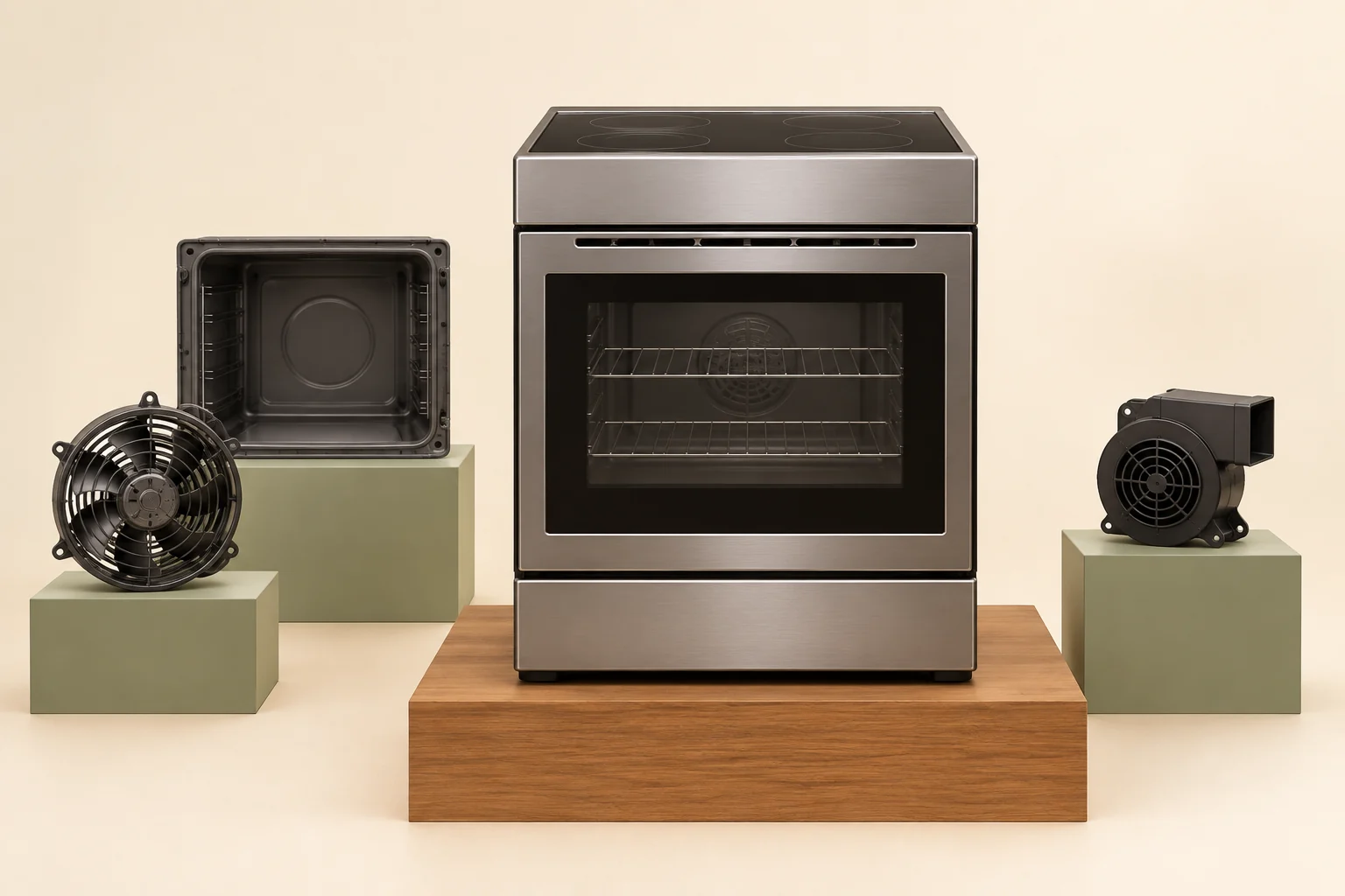
The central range has a closed glass-front door, two visible racks behind it, a narrow dark opening above the door and a blank fascia. At left, an independent empty cavity and a round grille-faced fan specimen occupy separate plinths. At right, an enclosed circular fan-like specimen with a rectangular outlet-like form sits on its own plinth. All specimens remain unconnected.
No detached specimen is identified as the actual appliance part. The display establishes no internal mounting, duct or wiring path, air direction, rotation, cooling circuit, temperature, safe-to-touch state, operating time, exact model or fault. The narrow opening is a landmark, not a proven discharge path. No kitchen hood is pictured; room exhaust needs the separate room-source explanation.
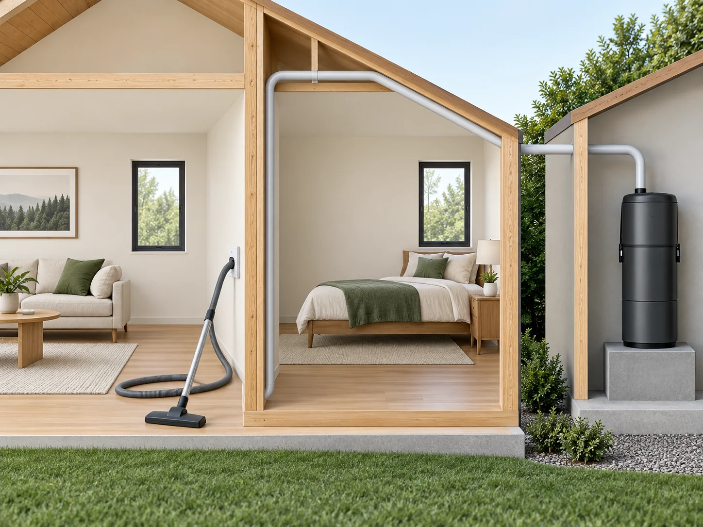
The tool and hose are in the room on the left. A pipe runs up and across the house frame towards the main unit on the right. The walls are cut away to make these parts easier to see.
This is an illustration, not a map of your home. The connection between the inlet and the rising pipe is hidden. The unit’s exposed display position is not an outdoor-installation example. Your documents and a technician’s findings establish the actual connections and equipment location.

The left example shows a bag inside a housing. The right shows a filter above a separate collection container. The parts are spread apart so you can see them.
These are different collection examples, rather than instructions for assembling or opening a unit. The picture does not identify your model or tell you whether a particular bag or filter can be cleaned. Use the instructions for your equipment.
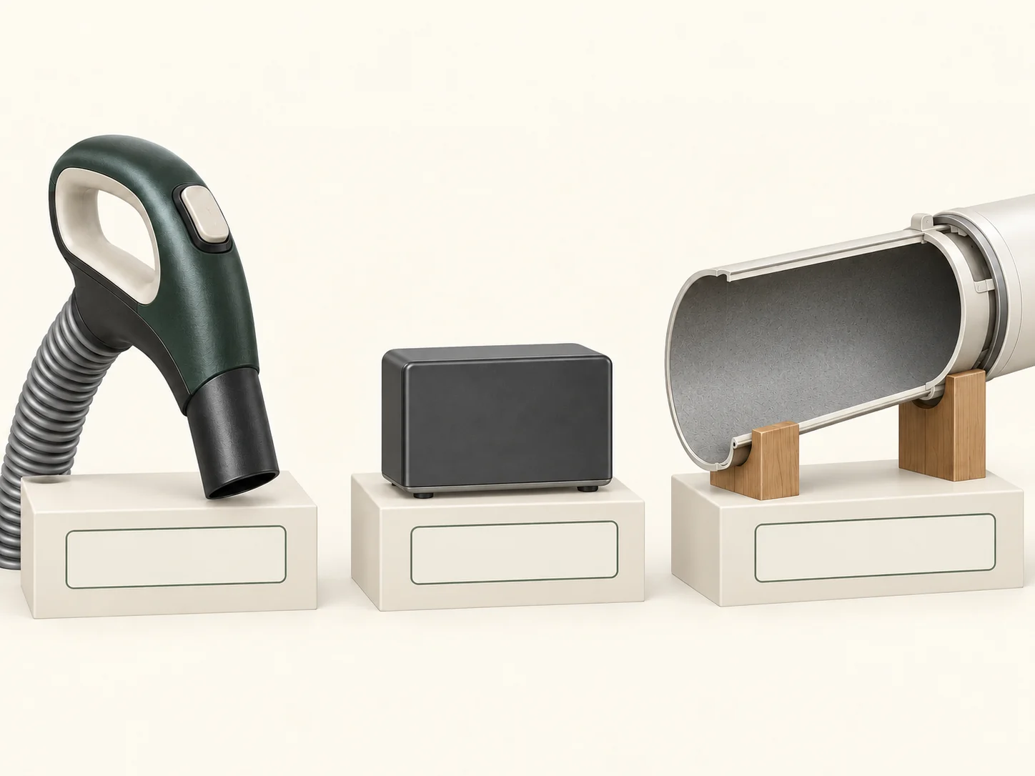
The handle, control-box example and pipe are shown separately. The handle tells the unit to start or stop. The pipe carries air and dirt.
The control box is a simplified example, not a particular receiver or wiring layout. The parts are disconnected, so the picture shows no working signal or airflow. Your manual identifies your system’s controls and compatible accessories.
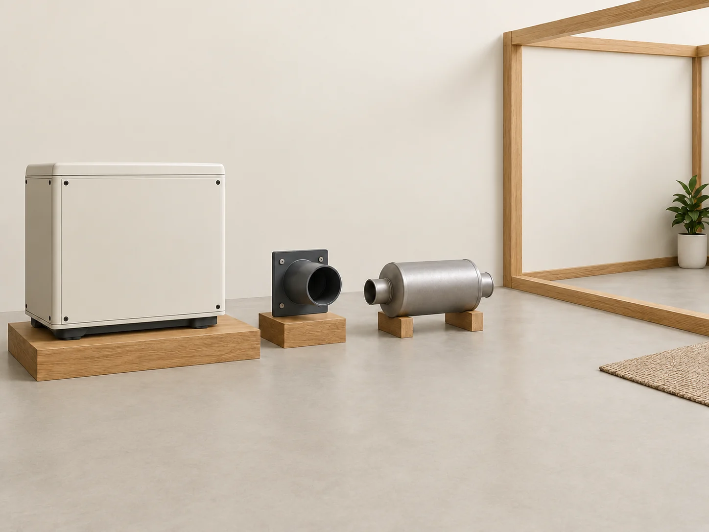
An equipment cabinet, round outlet and cylindrical muffler are shown separately beside a wall frame. The picture leaves out the connecting exhaust route.
This illustration does not identify your unit or show its exhaust destination. The wall frame is not a pictured outside termination. The actual equipment and installation records explain where the air goes; a nearby outdoor opening may belong to another system.
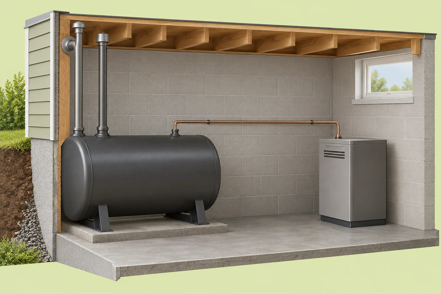
A closed horizontal grey vessel rests on illustrated supports at the left. Two capped vertical pipe forms rise from its top. A thinner copper-coloured line-like form is drawn between another top connection and the separate closed cabinet at the right. A short side fitting meets the partial wall near the left-hand pipe; two complete exterior endpoints are not shown.
The model identifies no actual fuel, manufacturer, tank construction, fuel level, fill/vent/alarm function, complete external route, product-line specification or flow, appliance purpose or condition, support adequacy, code compliance or approved installation. The capped top forms are landmarks; they do not demonstrate a working fill-and-vent arrangement. No caps, covers or fittings should be opened to reproduce this illustration.
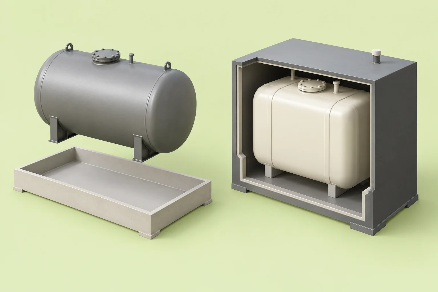
At the left, a closed grey vessel and empty shallow pale tray are separated vertically for display. At the right, a smaller ivory vessel sits on small visible supports inside a grey outer shell with its front cut away. Space is visible beside and beneath portions of the inner vessel; no liquid, leak or operating indication is shown.
This is an exploded and cutaway teaching composition, not a floating tank installation, identified commercial model or approved containment design. Actual vessel materials, capacity, continuity, integrity, monitoring function/state, local suitability and manufacturer instructions are unknown. No visible tray or outer casing proves sufficient containment capacity or covers other piping and historic storage.
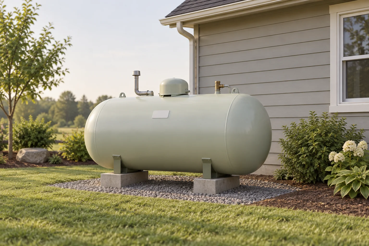
A pale closed horizontal vessel stands on illustrated supports and blocks beside a house wall. Gravel, lawn, planting, a roof edge and downspout context are visible. A small front plate is blank. Short top fittings and a domed top form are visible without identifying their functions.
The picture supplies no actual fuel, product/model identity, tank age, plate content, outdoor designation, internal corrosion, leak integrity, concealed route, support capacity, anchorage, measured clearance or weather-exposure finding. The tidy exterior is not an assessment, certification or remaining-life estimate. Top shapes are not identified as a fill, vent, gauge, alarm or approved component.
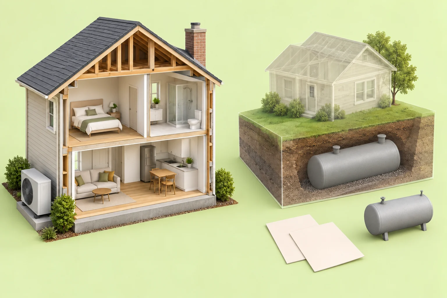
A furnished timber house cutaway and closed outdoor fan-cabinet form occupy the left study. A separate translucent house-and-ground display on the right includes a grey cylindrical buried-vessel landmark. A detached grey vessel on small feet and two blank paper sheets sit in front. The visible vessel surfaces are grey.
The studies are separate conceptual examples, not before-and-after evidence or a finding that the left house has buried storage. Actual current equipment identity/function, past oil use, tank presence/location, detection coverage, removal or disposal scope, retained piping/liquids, environmental condition and authority closure remain unknown. Neutral colouring cannot establish corrosion-free vessels, uncontaminated soil, completed removal or regulatory acceptance; blank sheets contain no reports, dates or results.
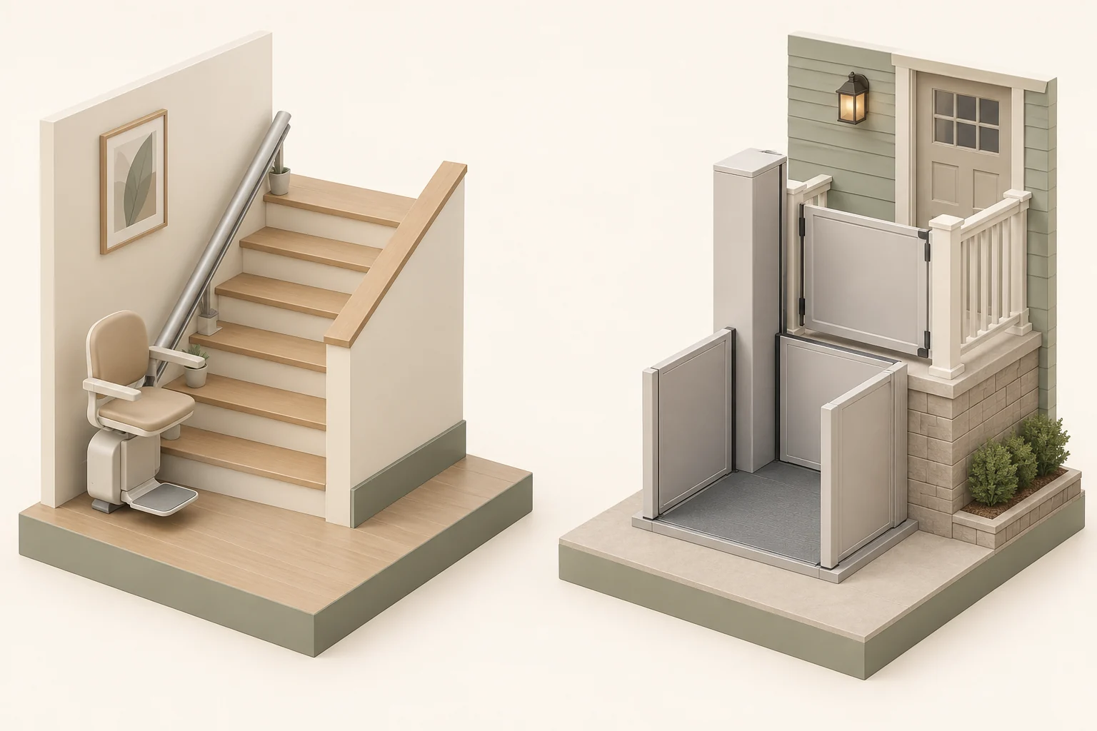
The left study has an empty chair with seat, back, arms and small footrest beside an inclined rail and stair treads. The separate right study has a flat lower platform between side panels, a closed tower-like enclosure and a closed upper landing barrier beside a raised porch. The lower platform’s camera-facing access side appears open.
The scene identifies no actual model, classification, capacity, support, user transfer ability, wheelchair fit, safe travel, entrance protection, interlock function, operating state or local approval. The open-looking lower access side is a display observation, not proof of an approved entrance or protection arrangement. The two studies do not establish equivalent household suitability or instruct operation.
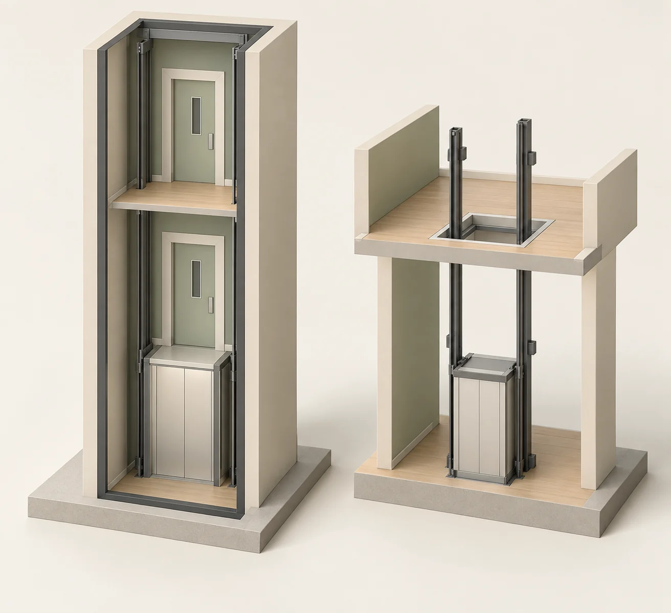
The left study has a tall enclosure with its front cut away, guide-like rails, a lower closed cabin-like box and two door landmarks at different levels. The right study has a rectangular opening in an upper floor, two guide-like rails crossing it and a lower closed cabin-like box. There is no person or travel sequence.
Actual product category, support, framing, floor-opening protection, guards, entrance alignment, clearances, enclosure/fire design, stops, drive, electrical supply, sensor function, capacity and approved installation are unknown. Open model fronts and floor opening are architectural display devices, not inspected access areas, safe unguarded openings or instructions to create an opening. Closed boxes do not prove travel or protective operation.
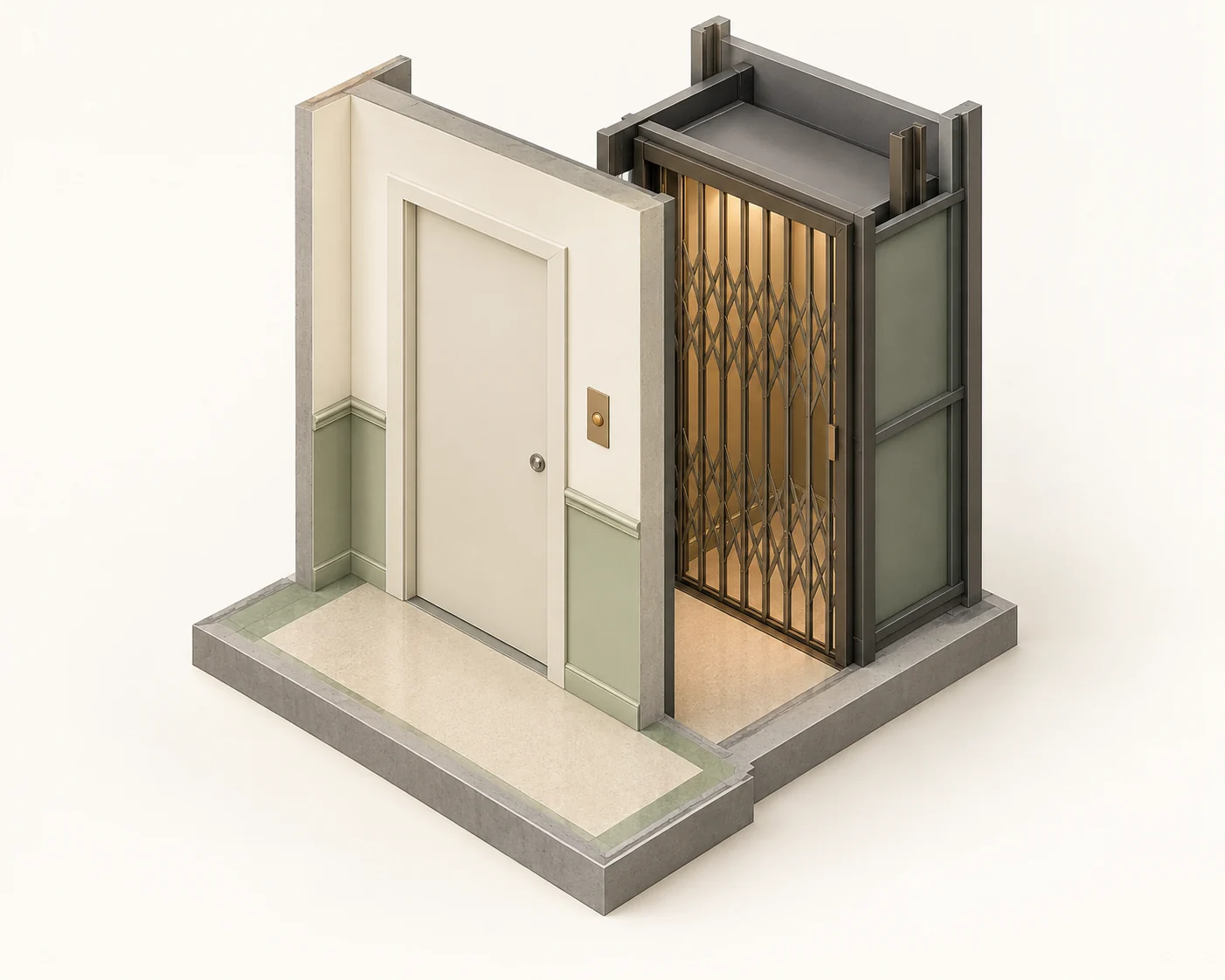
A closed flat door sits in a pale wall specimen at the left. A separate lattice-like gate is drawn closed across the cabin specimen at the right. The wall and cabin are offset so both layers can be seen; a small button-like wall landmark and surrounding frame are visible without an operating indication.
The offset is a compositional cutaway, not an actual entrance layout, safe access gap or clearance recommendation. No interlock, lock, gate switch, travel permission, trapping protection, installed alignment, door-liner requirement or present inspection finding is established. A button-like shape cannot prove a live control. No door or gate should be modified, forced, propped or defeated to reproduce or test the illustration.
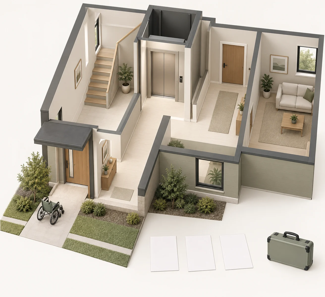
A home cutaway shows an exterior entrance, corridor-like floor areas, adjacent stairs and rooms around a closed elevator-like landing-door landmark. No cabin interior is visible through that closed entrance. An empty wheelchair sits outside. Three blank paper sheets and a closed case are separate foreground props.
The image supplies no actual device model, cabin interior, route widths, thresholds, turning space, floor levels, household-user fit, boarding, transfer assistance, accessibility certification, service availability, maintenance content or equipment condition. The empty wheelchair is a household-device landmark, not proof of fitting or safe independent use. Blank papers and a closed case contain no signed records, tools in use, completed service or approval.
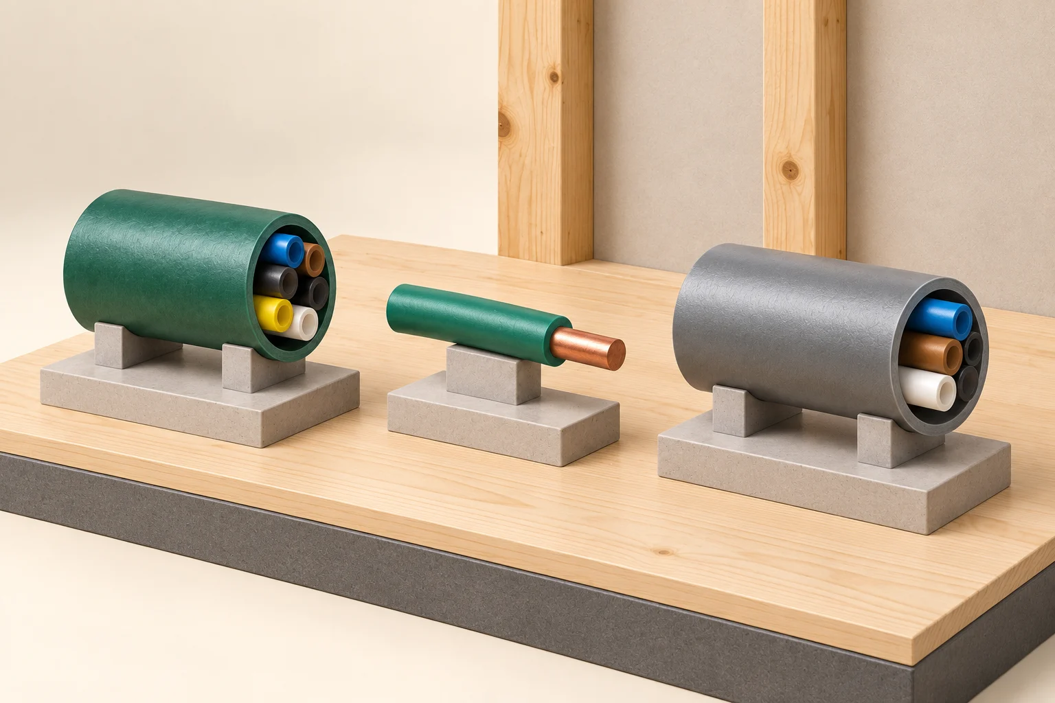
The outer jacket covers the inner parts of a cable. Here, green and gray shells surround several sleeve-like forms, while the middle green covering surrounds one copper-toned example. These enlarged teaching pieces do not identify a real cable.
The hollow inner sleeves are conceptual layer landmarks, not a complete cable cross-section. Metal, alloy, product family, conductor role, historical wiring type, certification and installed condition are not authenticated. No colour identifies a completed repair.
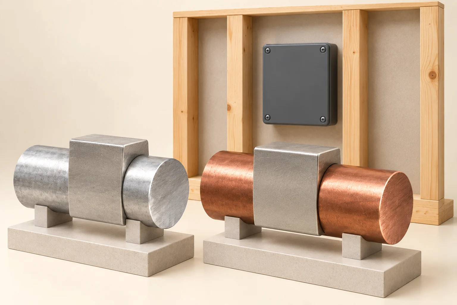
The two enlarged metal-coloured examples overlap broad blocks to introduce where parts meet. In a home, the conductor carries current and its termination joins it to equipment. These teaching shapes do not show an approved residential connection.
No alloy, contact pressure, oxide film, actual current, temperature, damage, resistance, approved terminal or safe connection is established. These solids are not a workable repair assembly or an instruction to adjust a real connection.
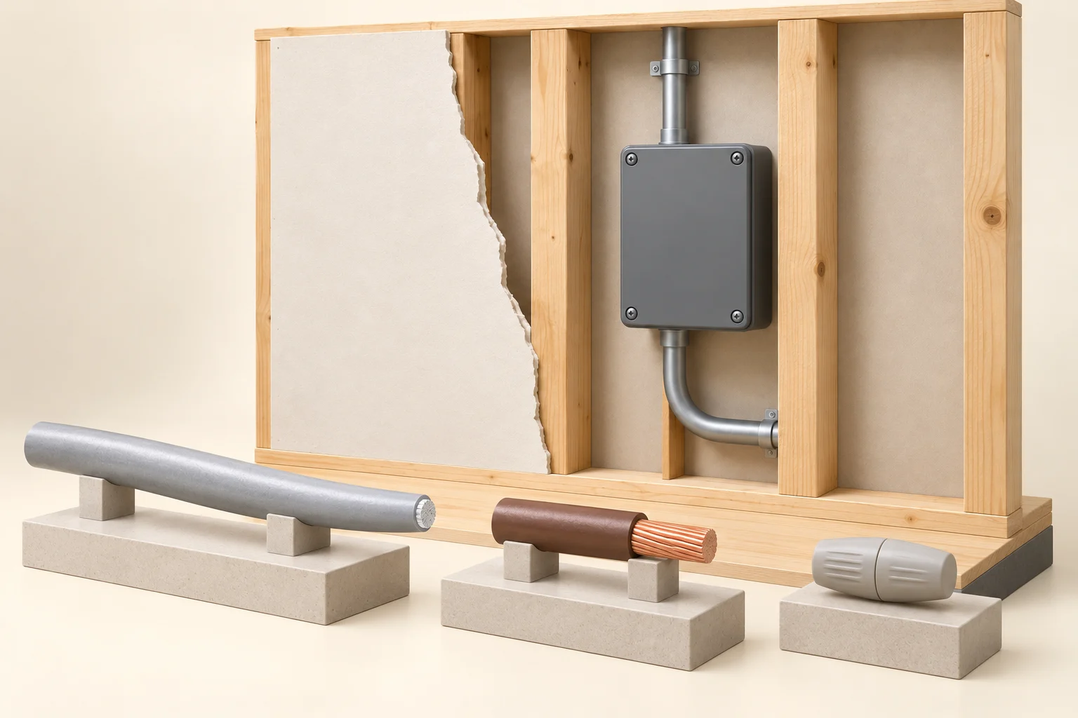
A long silver-toned specimen, a shorter brown-covered copper-toned specimen and a plain gray capsule sit separately. Both cut ends have strand-like detail. The wall enclosure is closed and none of the loose objects is visibly connected to it.
These oversized stranded-looking specimens are not a depiction of historic solid aluminum branch wiring, an authenticated connector, a connected pigtail, retained installed material or an approved repair. Their relative lengths introduce scope only; no route, size, method or condition is verified.
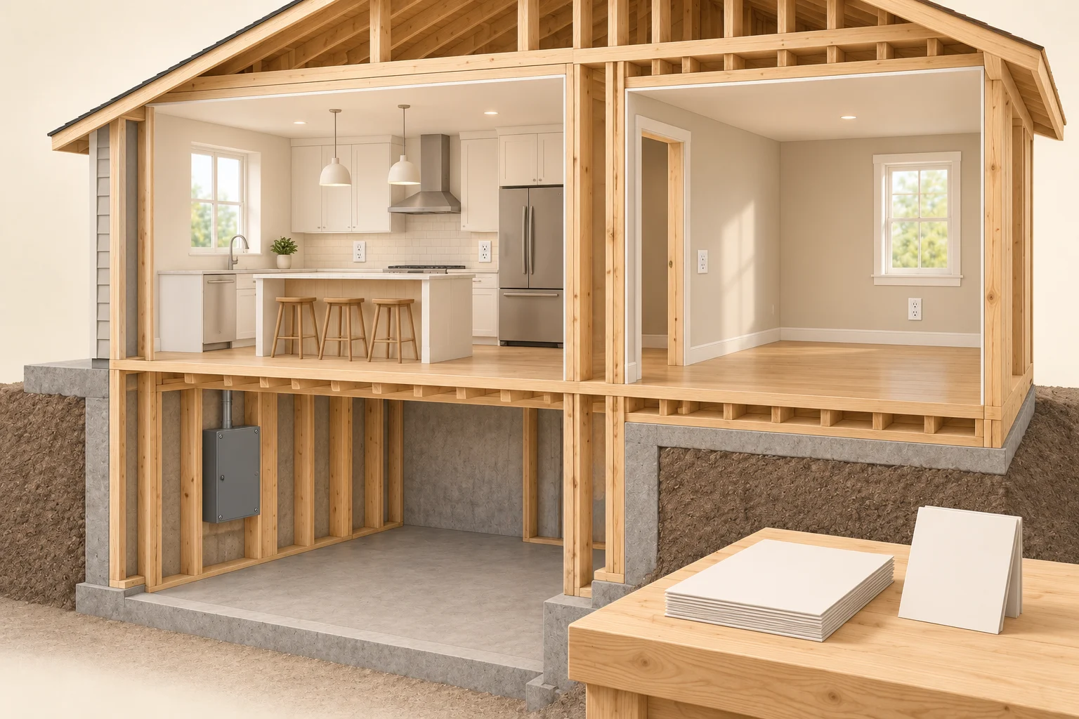
The basement has a closed gray enclosure. A kitchen and adjoining room have closed white receptacle-like faces. Timber framing separates the spaces, while blank sheets and a blank booklet sit apart in front.
No internal wiring, complete conductor route, conductor identity, hidden connection, actual assessment, completed work, approval, insurability or record content is visible. Selected room work cannot be expanded into a whole-house finding from this illustration.
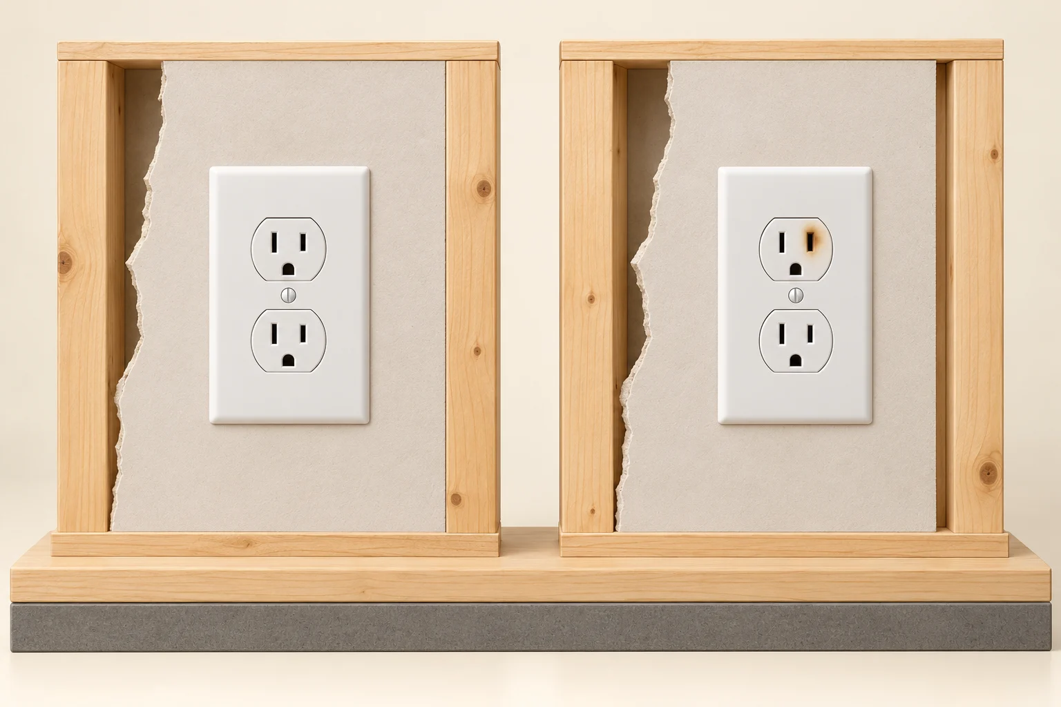
Both white receptacle faces remain closed. The right upper opening has a localized brown patch; the left face has no pictured patch. No plug, hand, tool, open device, smoke or measurement appears.
No aluminum conductor, heat, energized state, cause, concealed damage or safe-to-use condition is identified in either fictional specimen. An unmarked-looking face does not clear hidden connections; a surface patch is not an aluminum-specific diagnosis.
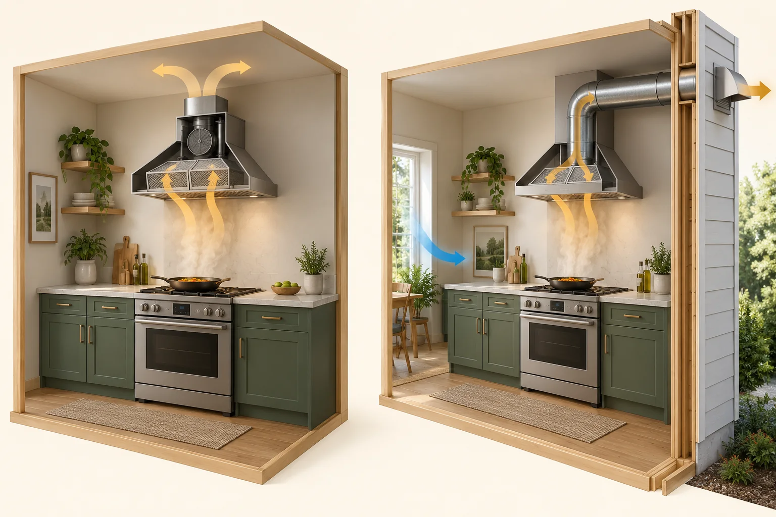
Separate kitchen models show cooking plumes, hood coverage, a return-to-room outlet on the left and an outdoor duct on the right. A blue arrow appears beside glazing.
The alternatives identify no actual product, filter performance, capture fraction, installed flow, approved duct, replacement-air design or healthy-air finding. The blue arrow does not prescribe opening a window or establish combustion safety.
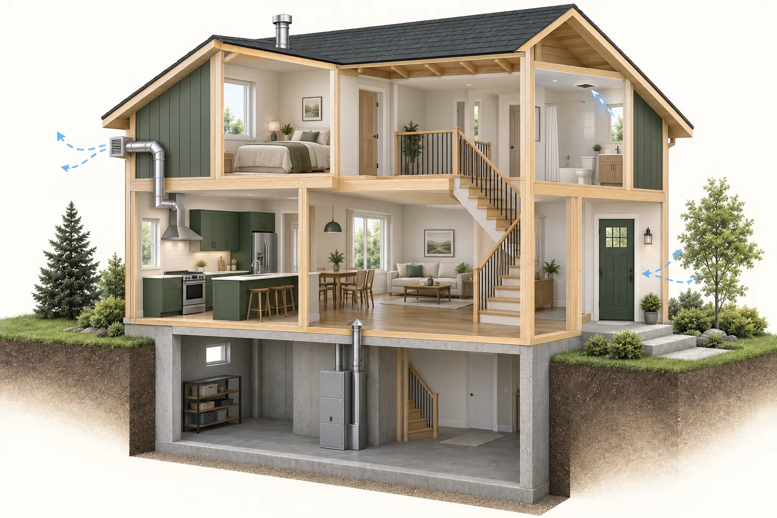
The hood has a visible illustrative duct reaching an upper exterior outlet. A bathroom grille, closed exterior door, closed gray cabinet and separate incomplete vent-like shape provide wider-house landmarks.
No appliance fuel, connected flue, roof termination, bathroom duct route, pressure, replacement-air route or safe operating combination is established. Dashed arrows are concepts. This is not a pressure experiment or an installation design.
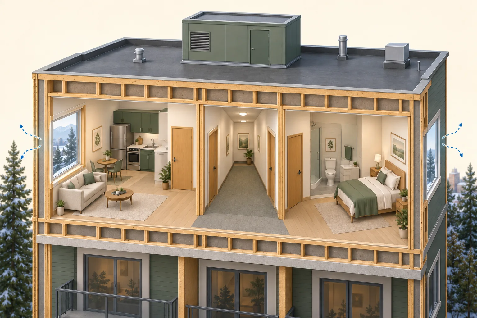
Two suite volumes sit beside a corridor with closed doors. Exterior windows have blue dashed arrows; a closed rooftop enclosure is another location.
The model identifies no installed supply/extract arrangement, pressure direction, source, measured transfer, outdoor-air capacity, health condition, ownership zone or access permission. Exterior arrows are possible relationships; the enclosure has no verified connection to suites.
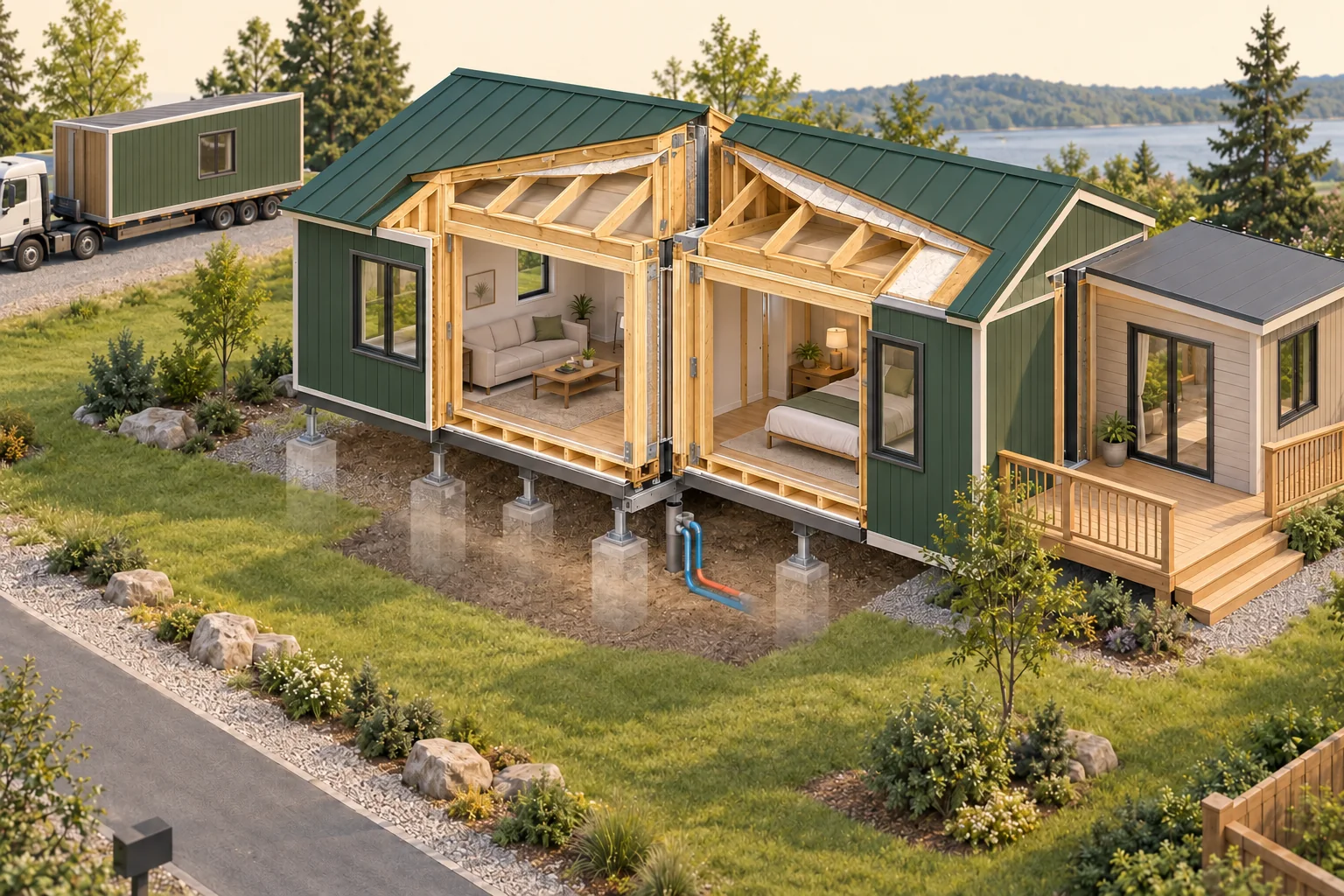
Two framed modules meet at a central junction. Simplified partly faded piers/supports and short service shapes appear below; a transport truck and added-room specimen give stage context.
No support design, capacity, anchorage verification, complete service route, legal boundary, title interest, certification status, transport finding or approved addition is established. Shown piers are illustrative rather than a design. The joined model does not define A277 or Z240 market classes.
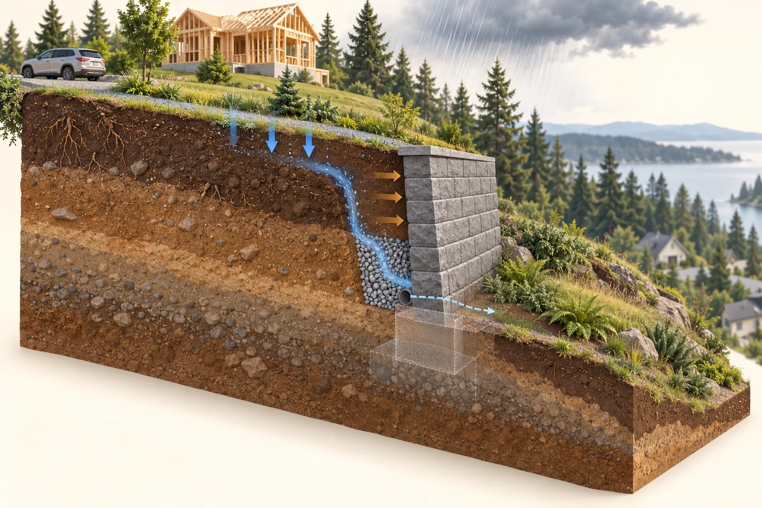
Higher soil sits behind a wall, with a vehicle and house farther upslope. Rain and soil-action arrows, a drainage specimen and a faded support shape sit within the wider terrain.
The specimen proves no soil properties, reinforcement, working drainage, outlet location or authorization, safe setback, capacity or slope stability. The downward route is conceptual and its dashed discharge remains unresolved. No dimensions or construction procedure are supplied.
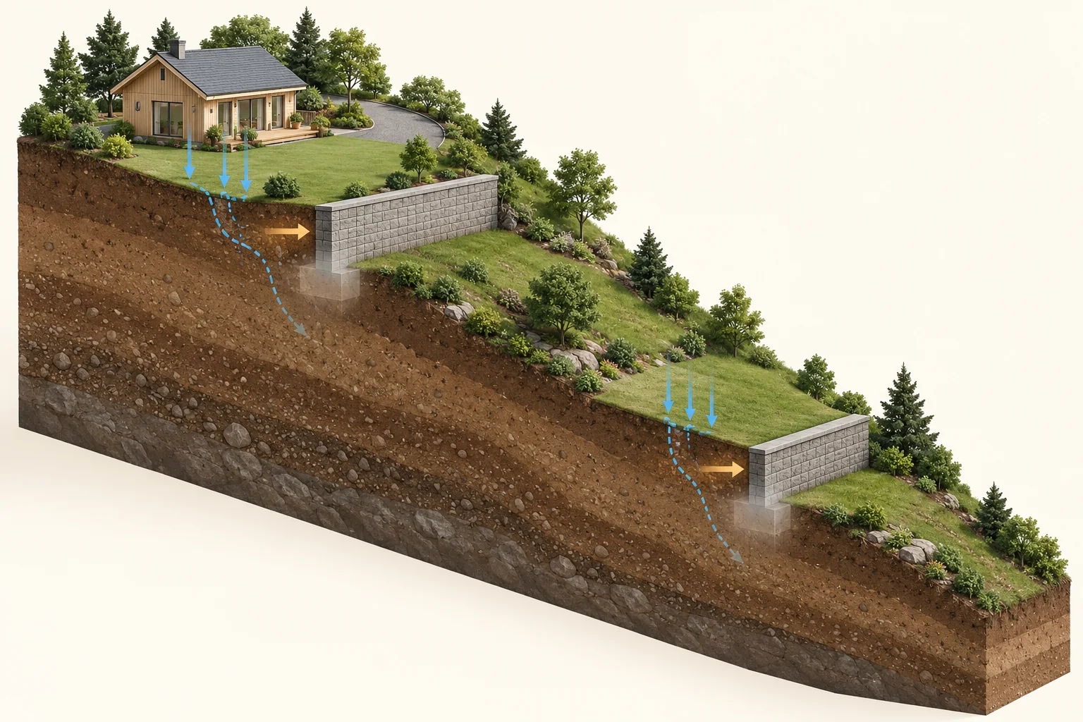
Two walls sit within one continuous slope. A house and driveway provide upslope context; dashed soil-water concepts and ghosted rectangular support shapes appear near the walls.
No wall design, support geometry, actual subsurface path, approved discharge, stable ground, safe distance or extent of wall interaction is established. A professional must evaluate the real slope and project; illustrated spacing is not a setback rule.
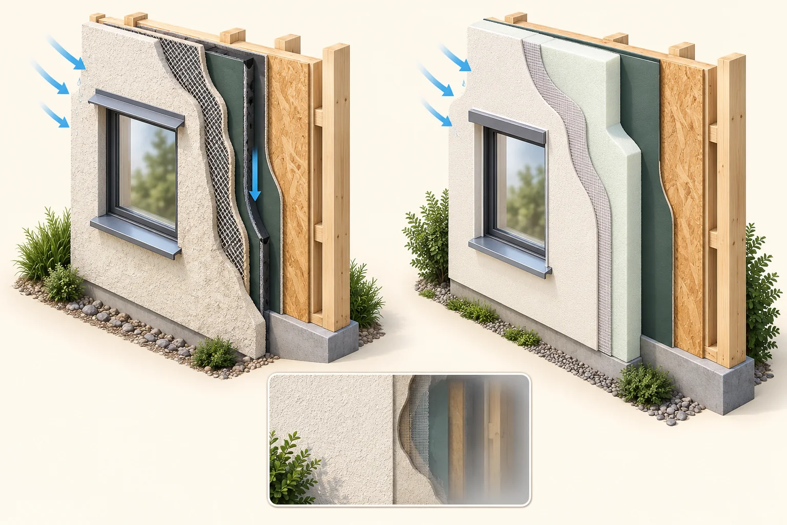
The left sample has a supported finish, separated zone, green layer and backing; the right shows a reinforced coating over exterior insulation. Both have window landmarks. A smaller finish/hidden-layer inset is below.
These are illustrative alternatives, not identification of a real wall or universal required layers. The right sample has no verified drainage path. Green colour establishes no material or continuity; metal shapes certify no flashing detail, fire rating, condition or compliant installation.
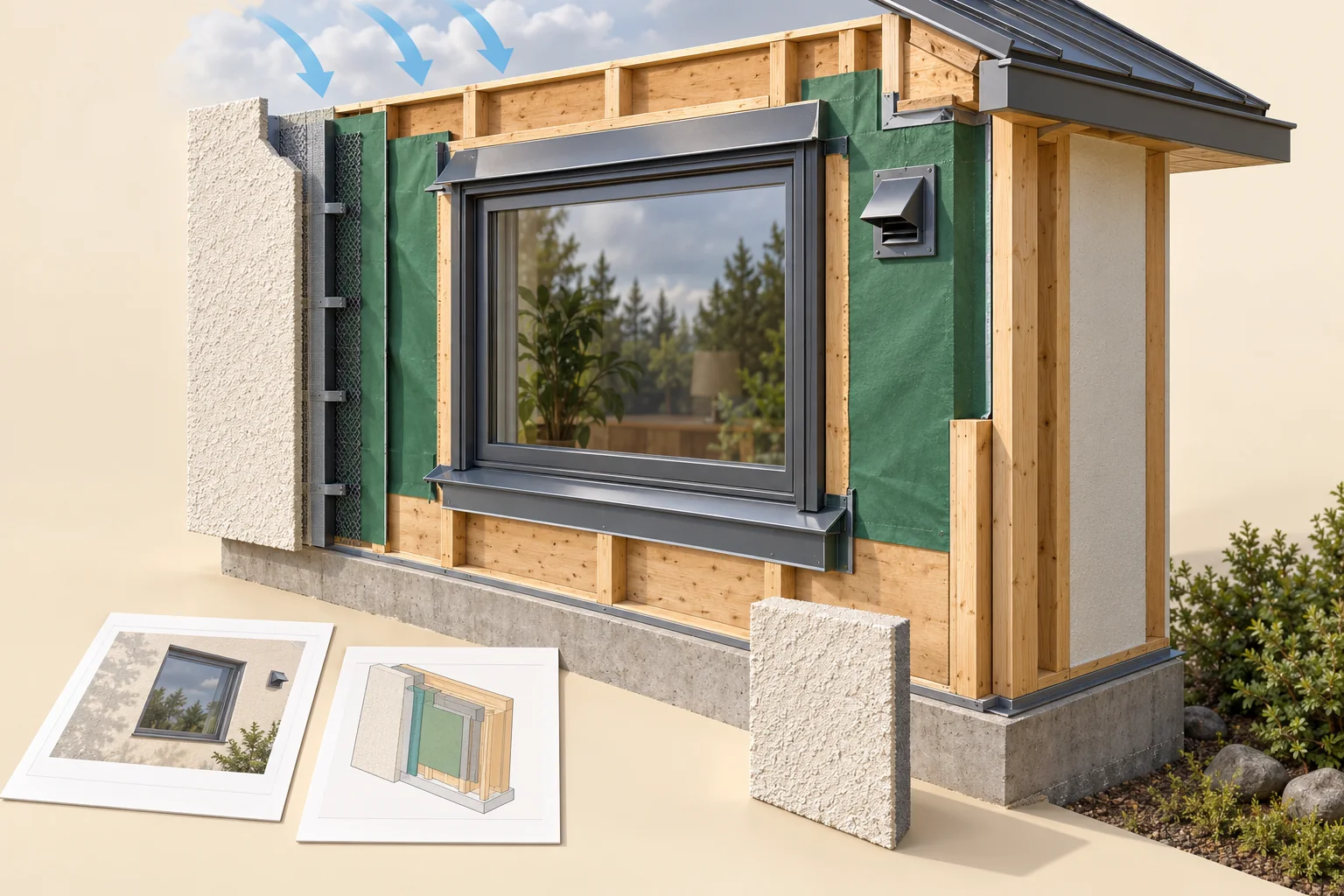
A large window, metal head and sill shapes, separate vent and roof-edge transition sit beside an exploded finish edge. A detached finish sample and invented photo/drawing illustrations lie in front.
These fictional illustrations are not property records. No interface integration, exact leak path, actual opened finding, concealed damage, approved detail or successful repair is established. Layer positions and metal shapes are not installation instructions.
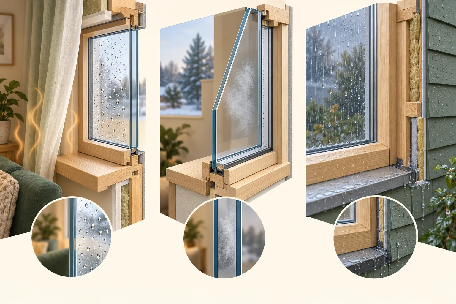
The left view has droplets beside an interior curtain. The middle tilts a pane for an illustrative glazing cutaway with haze between surfaces. The right shows a wet exterior face and frame context.
The tilted pane is a display device, not an opening or disassembly remedy. Exterior wetness alone cannot distinguish rain from exterior condensation or identify an entry route. No temperature, humidity target, sealed-unit diagnosis, mould finding or replacement decision is supplied.
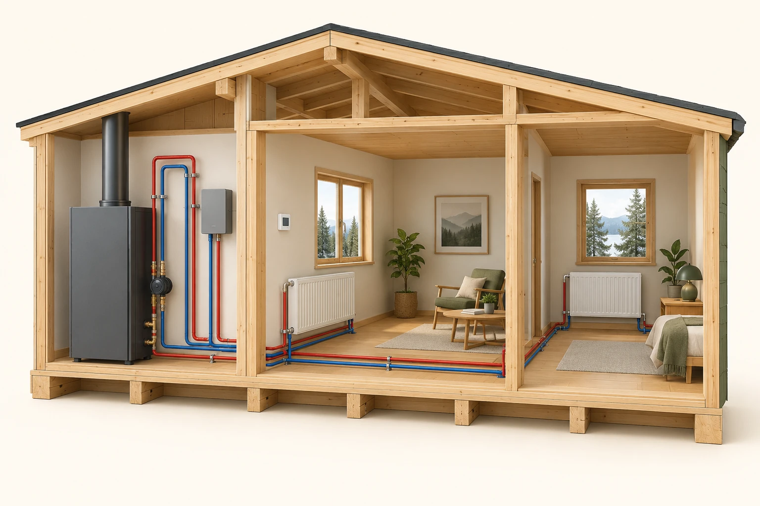
A tall closed cabinet, two finned room radiators and red/blue pipe forms are visible. The smaller grey enclosure has water-pipe connections. A plain wall device is shown. The colours distinguish drawn paths; the picture contains no temperature, flow or operating result.
The picture identifies no actual heat source, fuel, controller, independent zone topology, complete circuit, circulation direction, measured heat-transfer rate, room heat loss or approved installation. The smaller pipe-connected enclosure must not be identified as an electrical zone controller. No internal equipment access or adjustment is suggested.
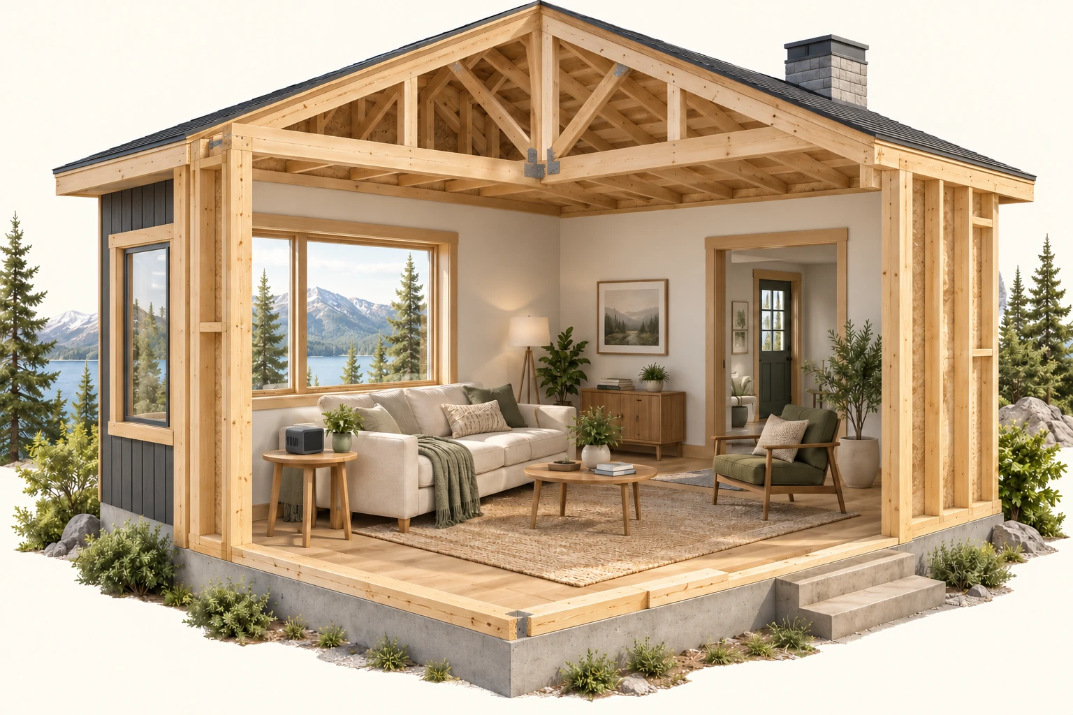
A small rectangular device rests on the left side table. Side slots and a blank dark front panel are visible. A closed window, furniture and an adjoining doorway provide room context; no reading, channel or instrument method is displayed.
The picture identifies no model, sensing channels, direct CO2 or estimated CO2-equivalent method, optical particle method, VOC method, calibration, averaging period, measured concentration, recommended placement distance or safe-air conclusion. One depicted position cannot establish room or whole-home coverage, and the device is not identified as a CO alarm or radon test.
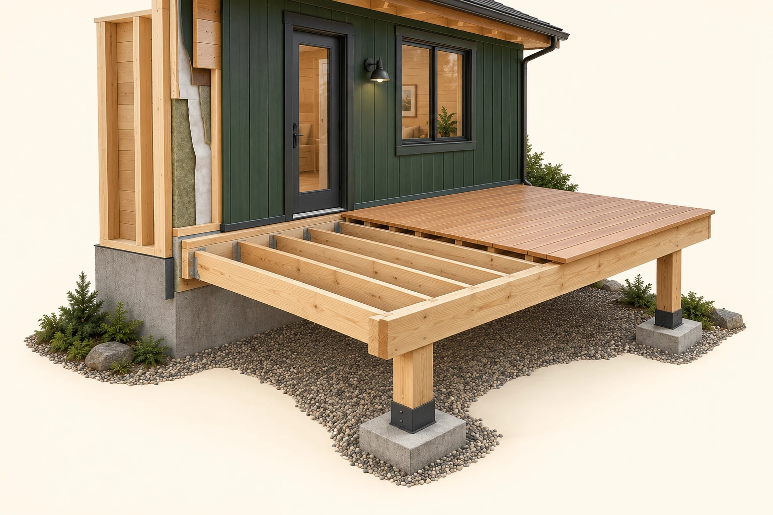
Joists, an outer timber member, two posts with bases and a house-side connection region are visible. A general wall-layer cutaway and doorway threshold place the deck beside the envelope. Metal connector shapes appear in the model.
The illustration supplies no structural capacity, approved ledger or connector detail, fastener schedule, backing condition, footing depth, frost design, water-control continuity, compliant guard or moisture finding. The cutaway is not an invitation to remove boards, enter underneath, test loading or copy a repair.
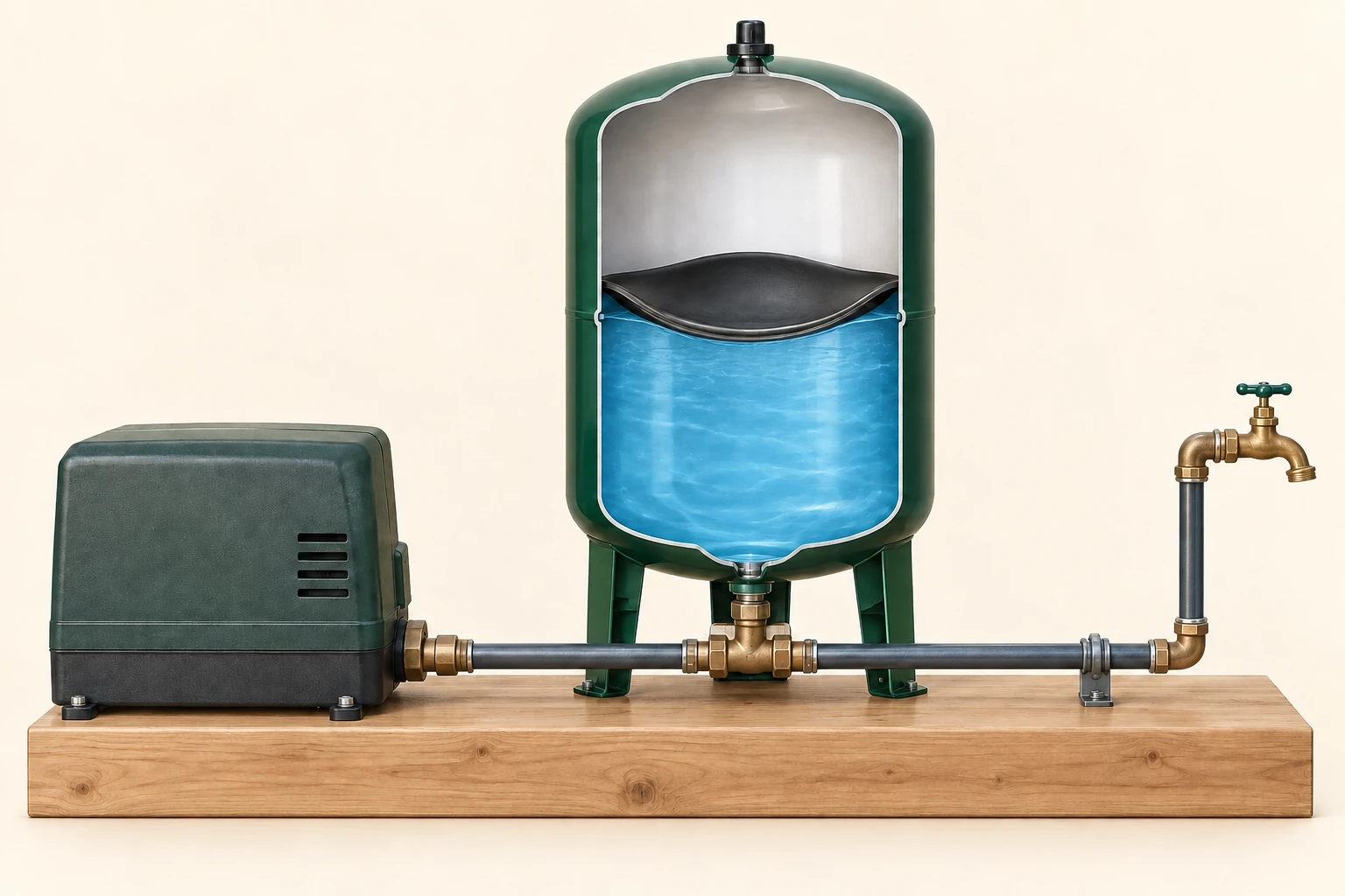
The curved diaphragm separates the visually empty upper air chamber from blue water touching its underside. A bottom branch connects drawn left and right pipe routes. A closed left enclosure and a right-hand tap are visible; the tap has no flowing stream.
This single conceptual position establishes no tank model, shell capacity, actual drawdown, pressure setting, air precharge, well replenishment, pump performance, bulk storage, outage duration or water-quality result. Drawn proportions cannot be converted to litres. The left enclosure has no established equipment identity. This is not permission to operate a private-well system during an outage.
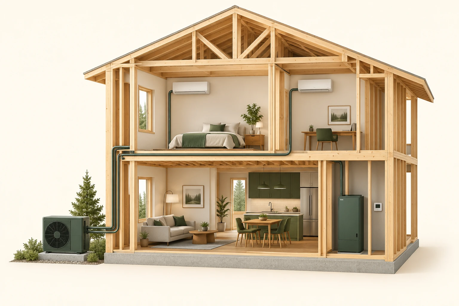
An outdoor fan cabinet and two upper wall-mounted room units are visible. Closed green paths relate the drawn components. A lower closed cabinet and plain wall device appear in the right-hand lower room; a tiny plaque-like patch is unreadable.
The image does not establish actual equipment identities, heating or cooling function, accepted component pairing, refrigerant or wiring topology, control sequence, supplementary equipment or fuel, room coverage, capacity, efficiency, certification or commissioning outcome. The lower closed cabinet has no established purpose. The coloured paths are not an installation schematic.
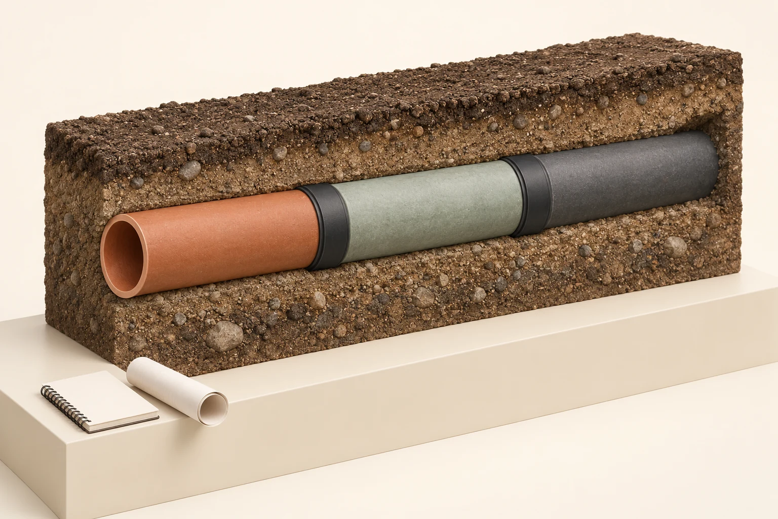
The soil block exposes the exterior of three coloured pipe stretches. Two dark band-like joints separate the middle stretch. The left mouth is open; the right stretch meets the far soil edge. A blank notebook and a separate cream-coloured hollow specimen sit on the plinth.
Colours establish no material identity, product, age or repair method. The exterior view shows no longitudinal interior inspection, liner bond, watertightness, diameter, gradient, bedding adequacy, located endpoints or legal boundary. The model is not footage, an actual repair, an approval or a condition finding.
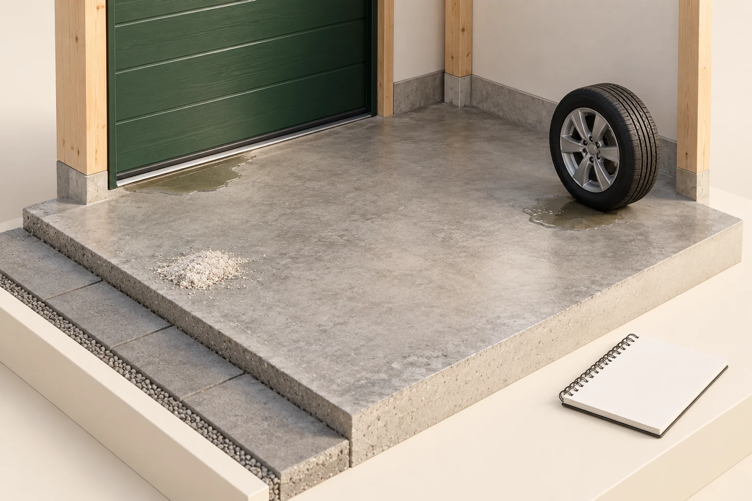
A closed green door and timber frame meet a concrete-floor specimen. Separate glossy patches lie near the threshold and wheel. Pale granules sit near the foreground; the slab face, outside paving and blank notebook are visible.
A glossy patch establishes no source, timing, volume or drainage route. Pale granules establish no chemical identity or confirmed salt. Surface texture and the slab face supply no moisture test, structural assessment, slope, coating compatibility or damage diagnosis. No actual property or operating vehicle is represented.
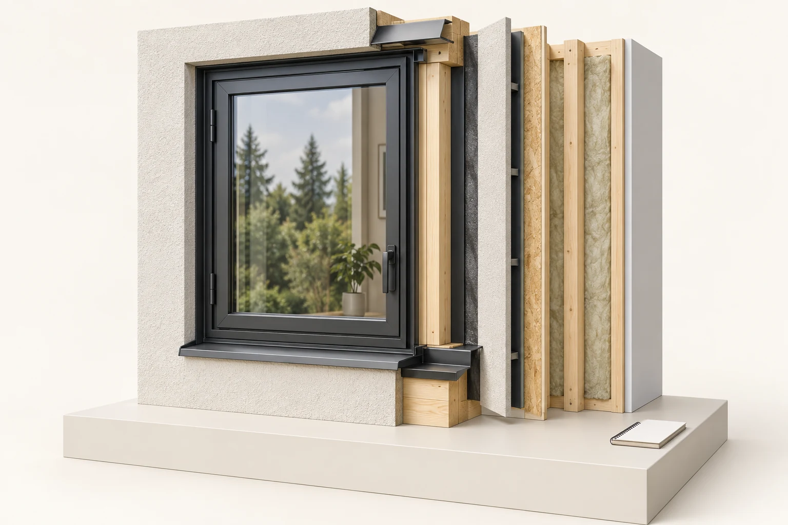
A closed graphite frame and glazing sit in a pale finished wall face. Hinge-like pieces and a handle-like piece are visible. The right-hand exploded specimen separates dark offsets, wood-like layers, studs, pale infill and a white panel. Short folded metal props appear at the head and right sill; a blank notebook sits on the plinth.
Hardware appearance does not establish operation, latch engagement, product identity, ratings or egress suitability. Exploded offsets establish no actual drained cavity, approved layer sequence or continuous air/vapour barrier. The short head and sill props establish no full-opening flashing, sill-pan continuity, slope, laps, outlets or drainage performance. No actual stain, defect, water test, repair or installation approval is depicted.
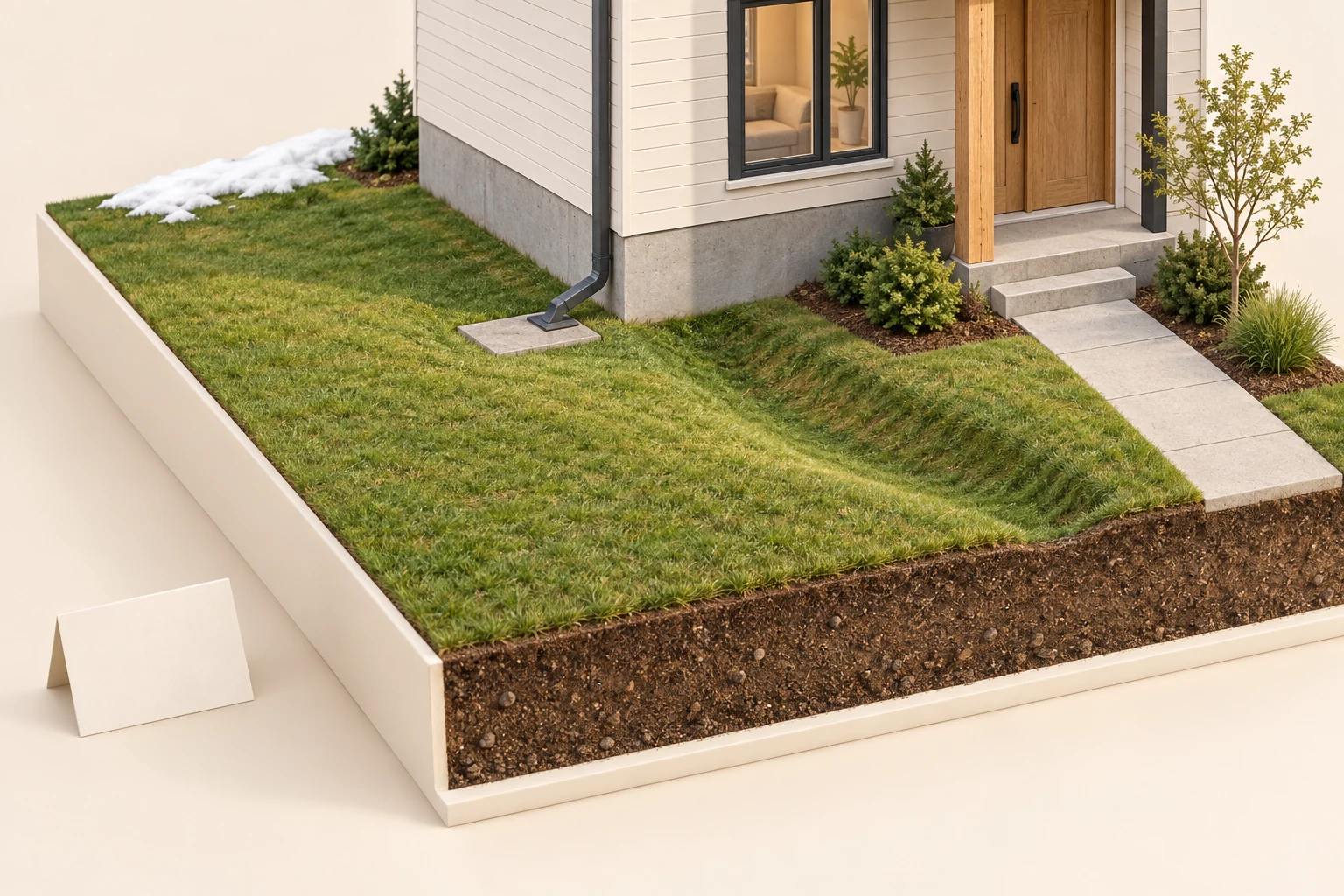
A pale house corner and grey foundation-style base meet a lawn. A graphite downspout ends over a rectangular pad. A concrete walkway is distinct from a curved concave grass depression. A small rear-left snow patch and a deliberate front soil slice appear; no buried pipes are rendered.
The stylized terrain supplies no surveyed elevations, true slope, flow direction, approved swale, drainage capacity, clearances, lot boundaries or grading acceptance. The outlet supplies no measured extension length, discharge adequacy or lawful destination. Bare lawn does not prove year-round performance or inspection completeness. The soil slice omits pipes as a teaching choice; it establishes no actual service absence, location or condition. No water, defect or repair finding is depicted.
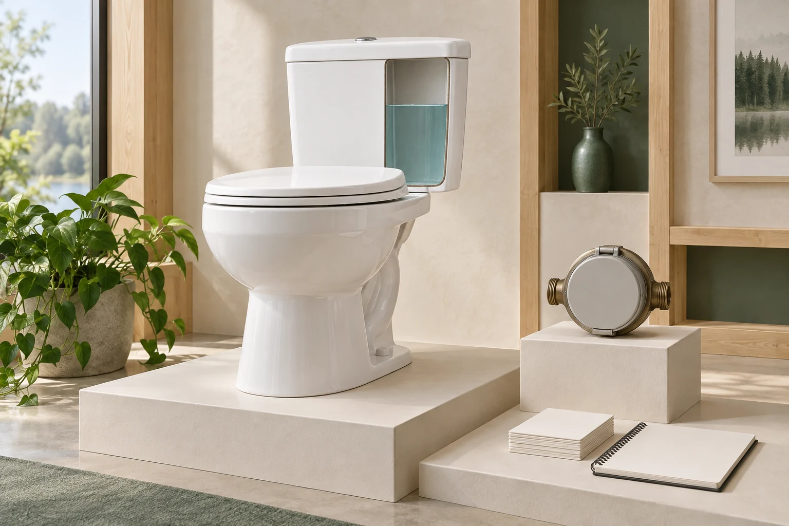
A freestanding ceramic toilet on a display plinth, closed seat/lid, a right tank window showing a static blue-tinted volume, a blank-faced circular metal prop with side threaded ports, and blank papers/notebook. The static tank specimen introduces a storage question; it does not depict the refill or flush event.
The fill valve, float, overflow, flush seal/flapper and supply/drain connections are not identified or exposed. The tank's static water depiction gives no measured level, timing, continuing flow, leak rate or leak diagnosis. The circular prop has no readable measurement, model or installed connections; its function and operating method are unestablished. The picture is not a usable anatomy/repair diagram, installed bathroom or safe-access instruction.
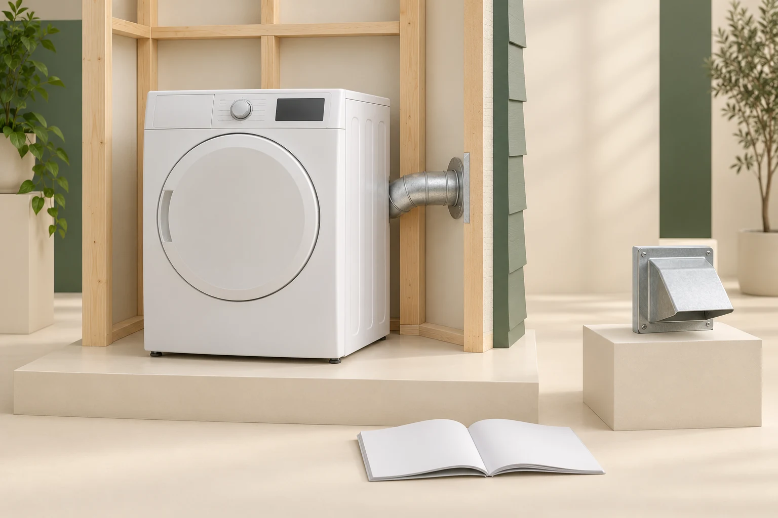
A closed front-loading appliance, exposed display framing, a short curved metallic section partly obscured beside/behind the cabinet and ending at a wall flange, green exterior-style cladding, a detached metal hood on a separate plinth, and an open blank book. Only part of the metallic section and its wall flange are visible. A complete concealed route is not drawn.
Appliance brand, model, fuel/energy source, ventilation type and operating condition are not established. The cabinet connection and any concealed continuation of the route are not fully visible; the image supplies no total length, diameter, bend allowance or equivalent-length calculation. The hood is detached, not shown installed on an outdoor end of this route. Its internal damper, screen status and operating movement are not established. No lint accumulation, blockage, airflow, temperature, drying result, termination performance or diagnosis is shown. Framing/penetration/connection geometry is conceptual and supplies no approved material, support, fire-separation, clearance, sealing or manufacturer-compliant installation detail.
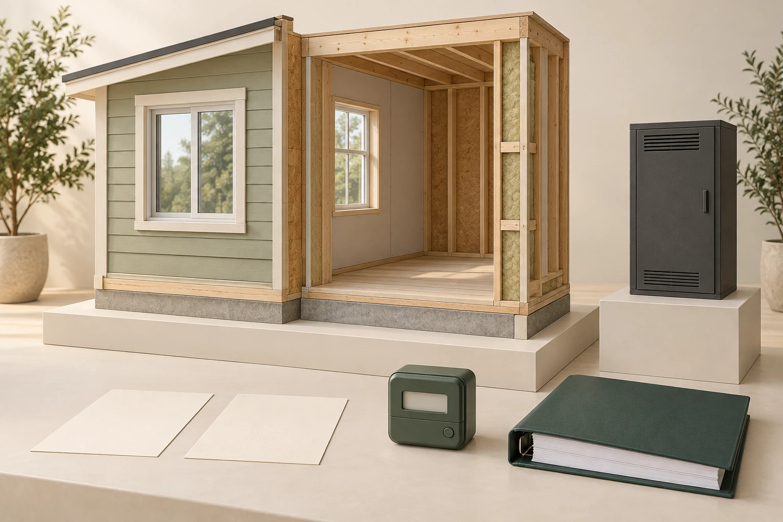
A small house-section model with a closed window and cladded face, exposed timber and fibrous-looking infill on another face, a plain dark vented cabinet on a separate plinth, a small green blank-display object, two blank sheets and a forest-green document binder. The sheets and binder are blank. They provide no consumption period, energy quantity, read status or due date.
Infill material, thickness, R-value, air/vapour/water-control continuity and assembly compliance are not established. Window product, glazing performance, leakage, installation condition and whole-home thermal result are not shown. The dark cabinet's equipment identity, fuel, capacity, efficiency, installed connections and operation are unknown; do not identify it as a furnace, heat pump or certified device. The small display object is detached and blank; no installed utility meter, energy advisor instrument, measurement, units or performance result is shown. No actual EnerGuide label, ENERGY STAR certification, utility bill, installation invoice, forecast or before/after data is readable. The model cannot prove a completed upgrade, building energy rating, measured savings, causal attribution or future bill.
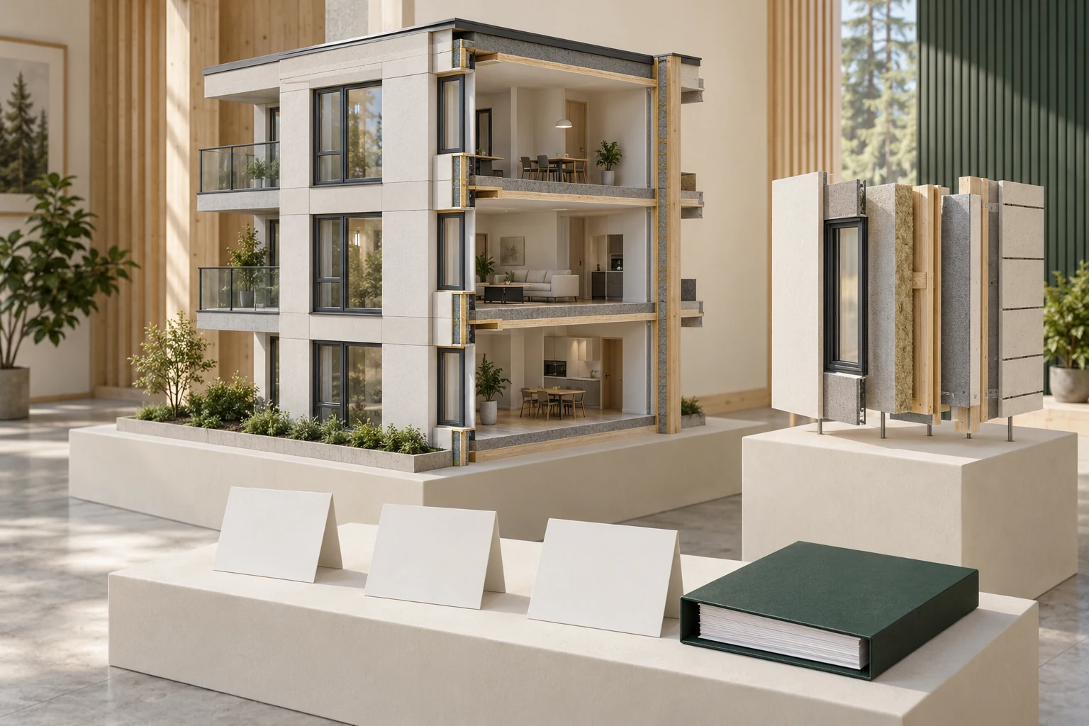
A three-storey apartment-like building model with a white exterior face, window groups, balconies, an open side exposing furnished floor levels and edge layers, a separate exploded wall/window specimen supported on rods, three blank cards and a forest-green binder. The detached wall specimen is a conceptual category. It is not a tested opening, verified material or investigation of the depicted building.
Built form does not establish condominium/strata tenure, unit/common/limited-common ownership, repair responsibility or document entitlement. The building and specimen have no actual inspection, defect, water entry, recommended repair, contract, phase, funding or completion status. Outer-face and infill material identities, layer ordering, flashing, anchorage, fire/acoustic separation, guardrail safety and approved assembly details are unestablished. The detached exploded specimen is conceptual and cannot prove construction at any depicted facade location or a suitable renewal design. Blank cards and binder are not real reports, executed drawings/contracts, approved resolutions, completion certificates or warranty records. No depicted geometry measures assessed/contracted/completed coverage or indicates a cleared/fully repaired building.
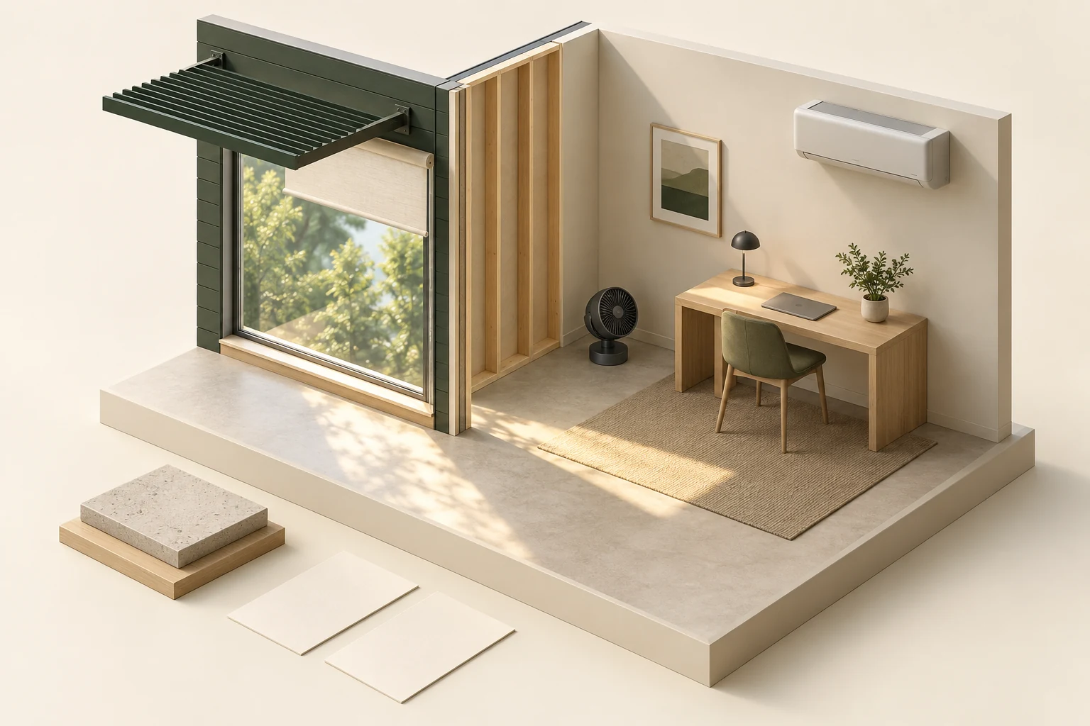
The room model shows an exterior blade shade, a closed window with a roller shade at the glazing, a sunlit floor patch, a guarded room fan and a separate closed wall unit. A desk, lamp, closed laptop and detached stone-like specimen are also visible.
Window ratings, orientation, shade effectiveness, actual gains, surface temperatures and appropriate installation are not established. The attached shade form supplies no anchorage, approval or saving percentage.
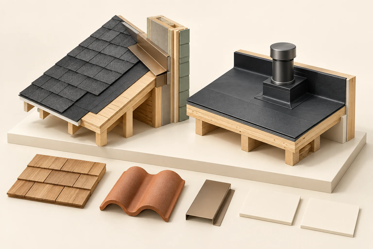
The model separates a pitched shingle-like roof-to-wall specimen from a dark low-slope specimen with a raised curb and closed cylindrical form. Detached wood-like, tile-like and folded metal specimens and blank cards sit in front.
The specimens provide no verified overlaps, concealed continuity, fastening, flashing sequence, water path or approved installation. In particular, the continuous metal form beside the wall is not an approved step-flashing or waterproofing detail.
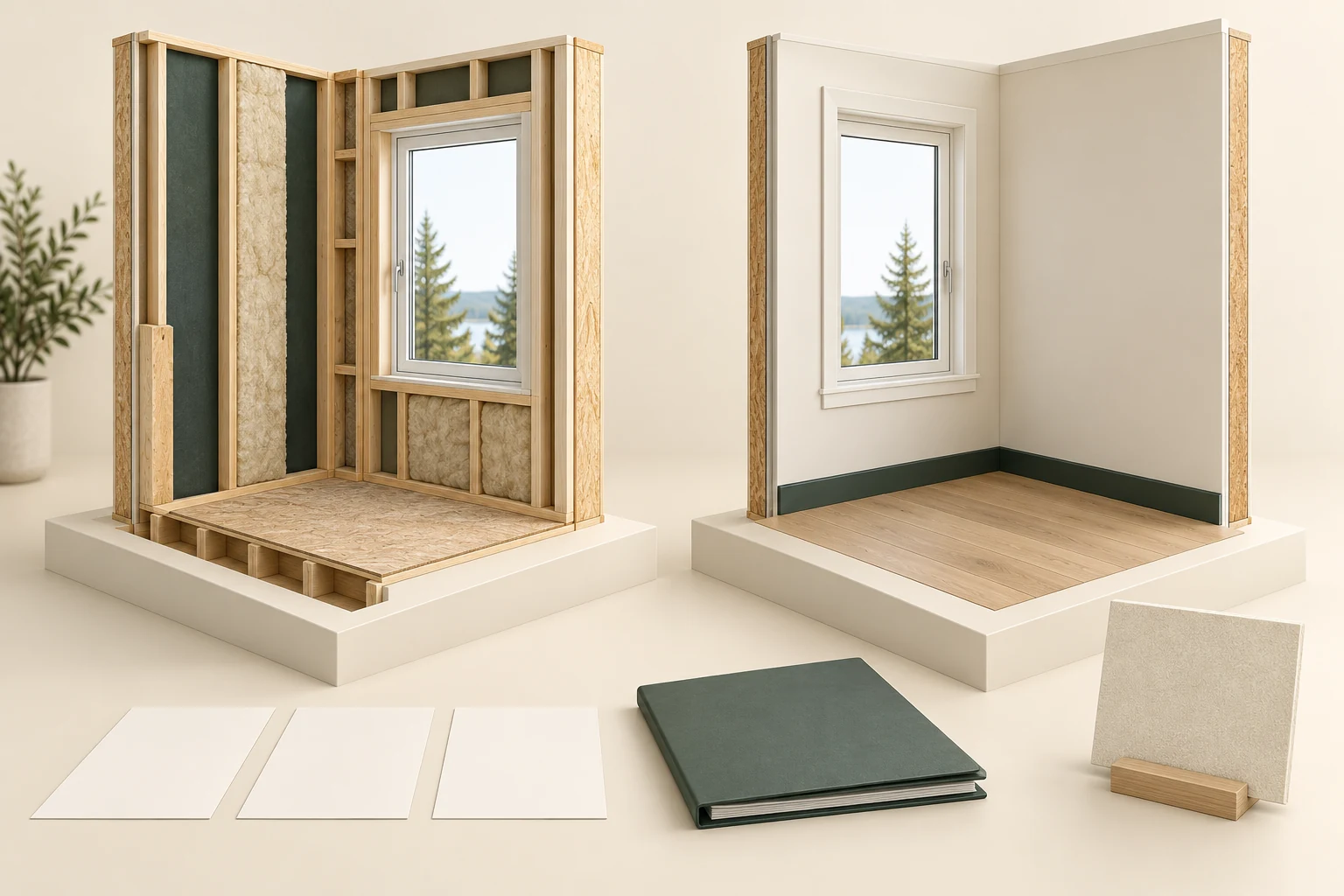
An open timber wall/window specimen appears beside a finished room/window specimen. The open view includes dark sheet-like and light infill forms and a deck edge; the finished view conceals those details. Three blank cards, a closed folder and a separate finish specimen sit in front.
The illustration establishes no actual stage, address, inspections, deficiency resolution, commissioning or right of access to a construction site. The two corners are conceptual views, not a verified same-property before-and-after sequence.
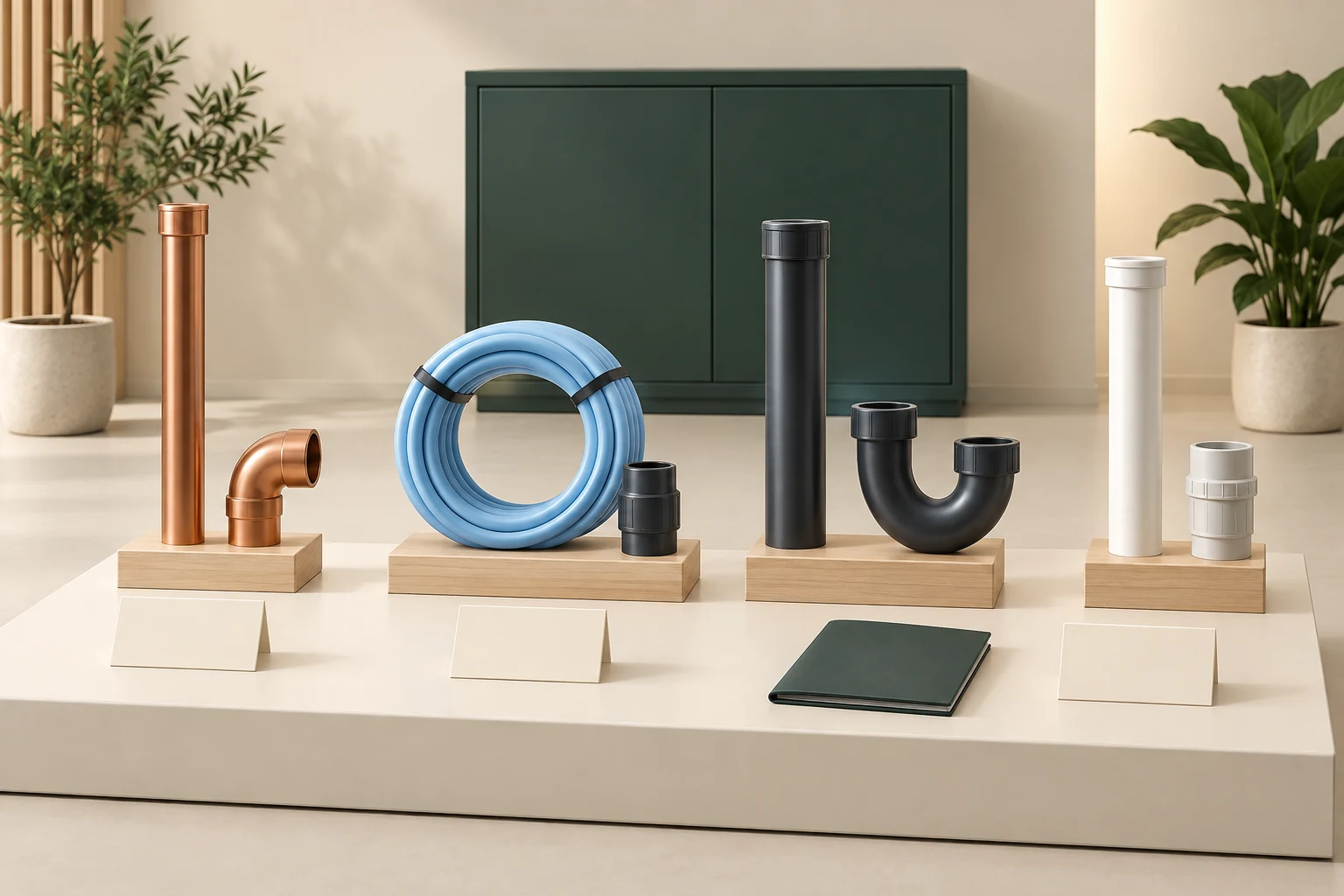
Pipe lengths carry water or serve a drainage and venting route; fittings connect those lengths and change direction. A flexible run can follow a curve, while an elbow changes direction at a joint. The important buying question is whether the identified pipe, fittings and application belong together. A newer supply branch can still meet an older system at a connection that needs its own record.
These loose parts have no readable product markings or completed joints. Colour and shape cannot identify their material or compatibility. Actual product information, locally applicable requirements and a qualified assessment are needed for the installed system.
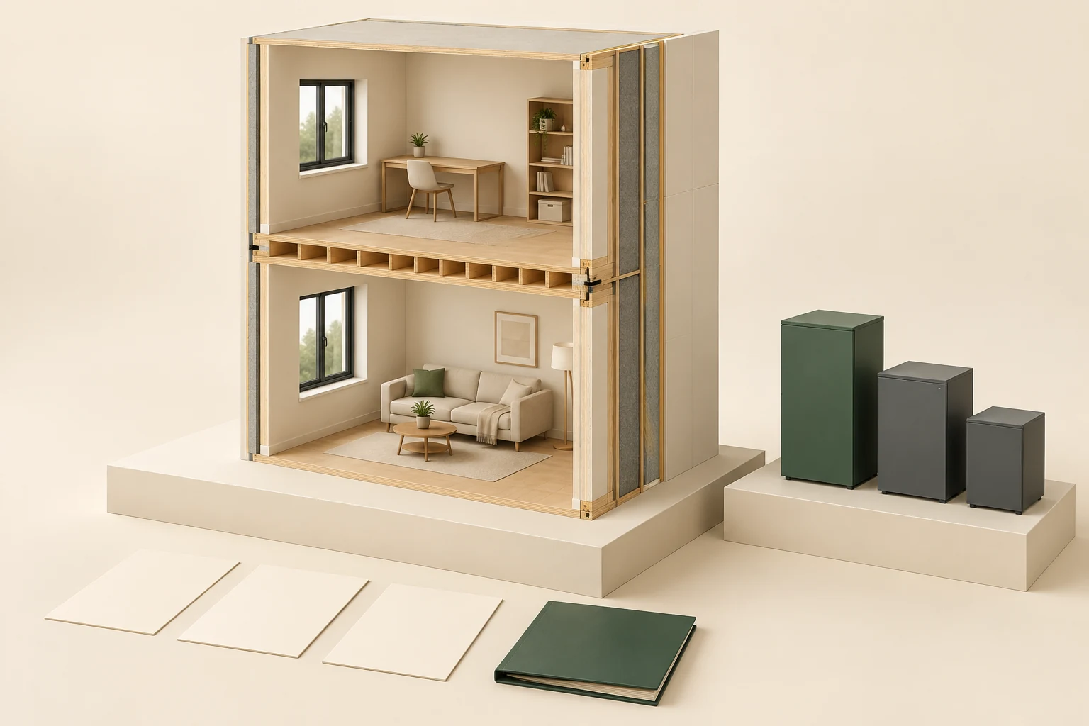
Two room spaces are stacked around a horizontal floor/ceiling specimen. The exposed timber and outer wall edge are conceptual interface landmarks, rather than a complete construction detail.
Neither interface certifies a property boundary, party wall, fire/acoustic/structural performance, actual service route, access right or legal responsibility.
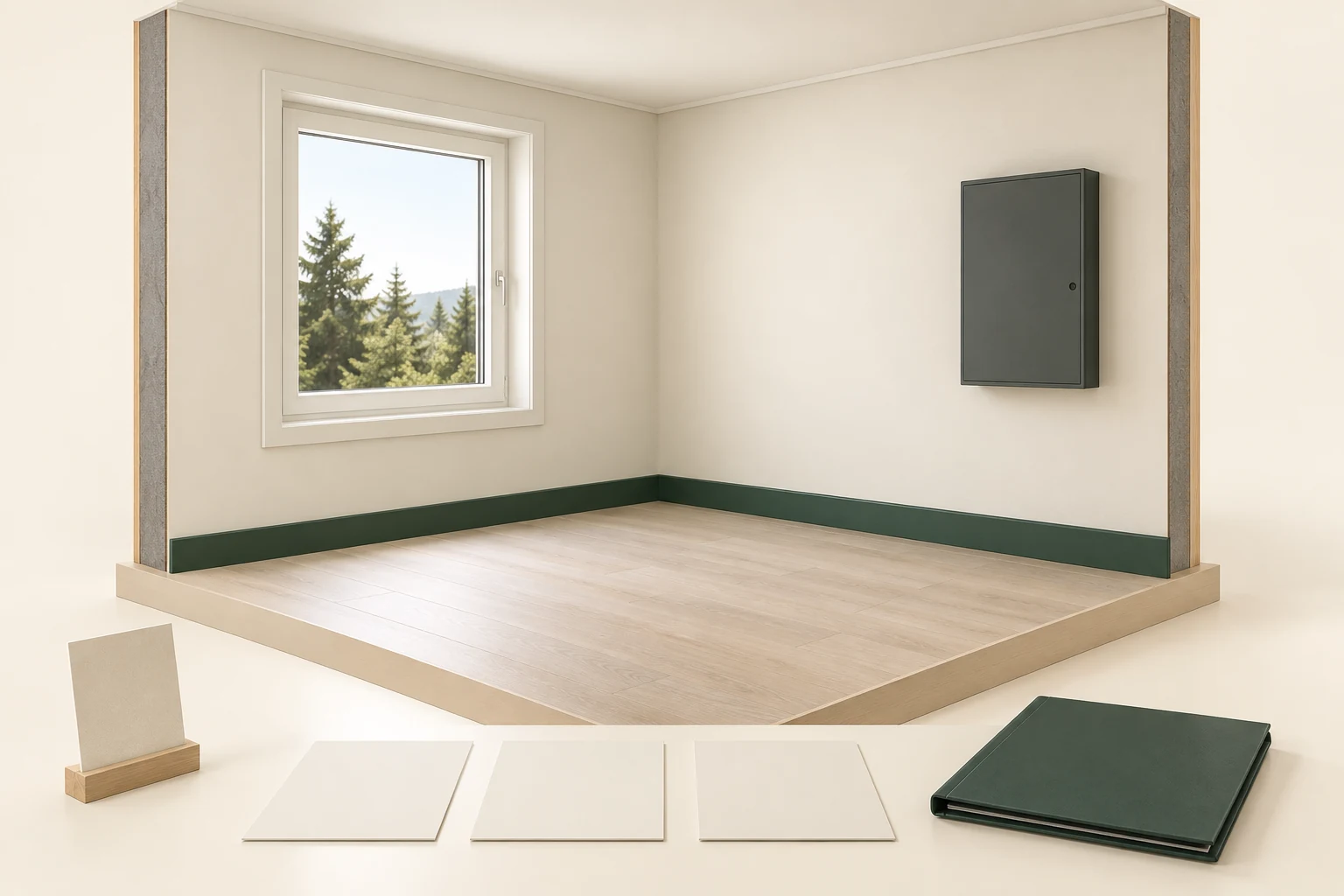
Intact finished surfaces are visible in a conceptual room corner. The separate sample and blank cards carry no material identification, date or assessment result.
The picture establishes no material composition, asbestos, lead, concealed layer identity, contamination, exposure, construction year or safety finding. Keep the finished surfaces intact.
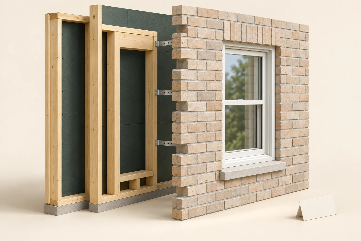
The brick face meets the weather; the timber frame sits behind it. The cutaway separates them so you can see that the outside finish and the wall behind it have different jobs. The window and its lower sill show where those jobs meet at an opening.
The layers are pulled apart for teaching. The dark backing has no identified product, and the picture leaves out the complete water-control layers, flashing and drainage openings. Connector shapes are illustrative, not a masonry tie specification.
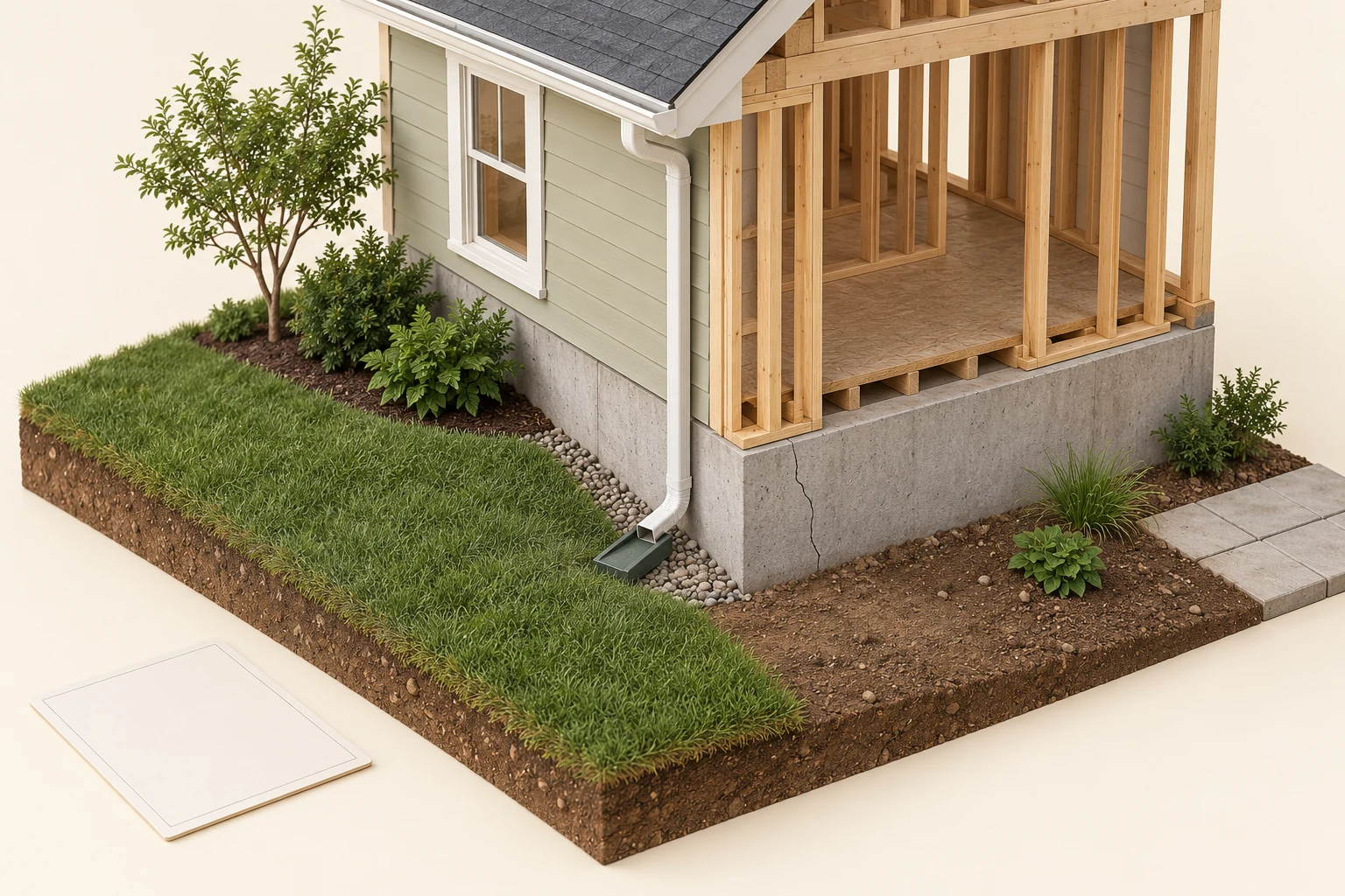
The foundation supports the house above it. Beside the wall, a downspout brings roof water to a splash block, while the yard provides the next part of the surface-water path. The drawn crack gives us a place to discuss an observation; it is not a finding at a real home.
The scene supplies no crack measurements, movement history, surveyed ground levels or observed water flow. It cannot identify the cause of a real crack or establish structural condition. Local grading requirements and any repair need a property-specific assessment.
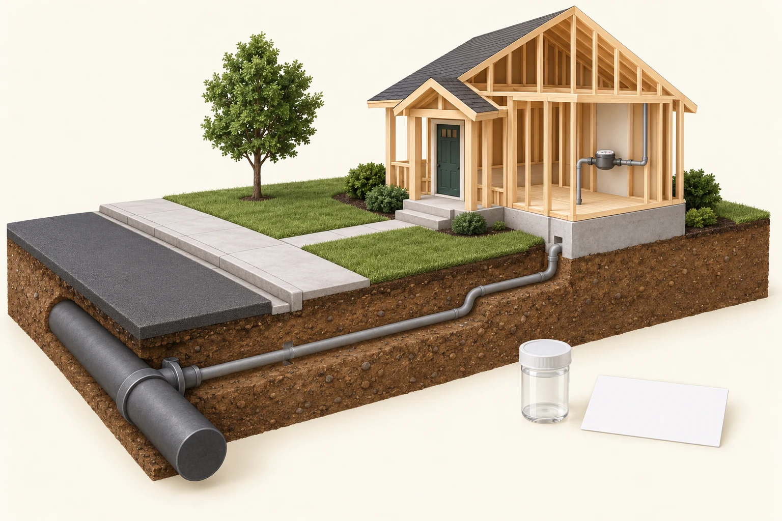
The large water main carries the street’s supply. A smaller service line brings water across the yard into the house, where a meter measures water use. Following these parts helps you locate the home’s water entry and match a repair record to the section of pipe it actually describes.
The pipe depths, sizes and grey colour are illustrative. Use property-specific records to establish real locations, materials and who maintains each section. Part of the indoor connection is hidden; no water-test result, measured pressure or winter protection is shown.
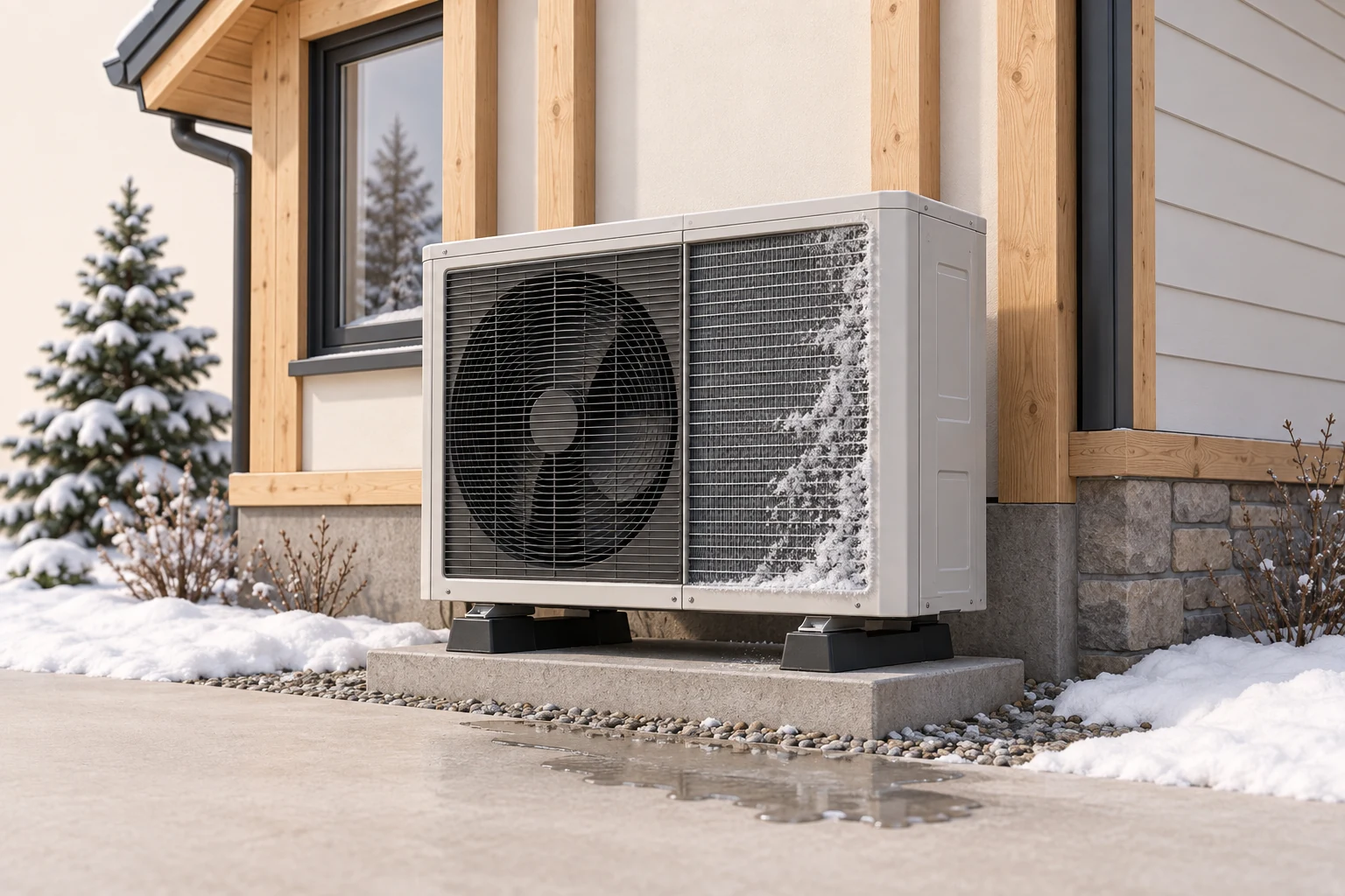
The illustration shows a fan grille, part of a finned surface with frost, snow nearby and water on the ground. It is a teaching scene, not a photographed installation.
The actual coil arrangement, operating mode, event sequence, weather, temperature, drainage route, clearances and cause remain unknown. Frost or a puddle alone establishes neither normal operation nor a fault.
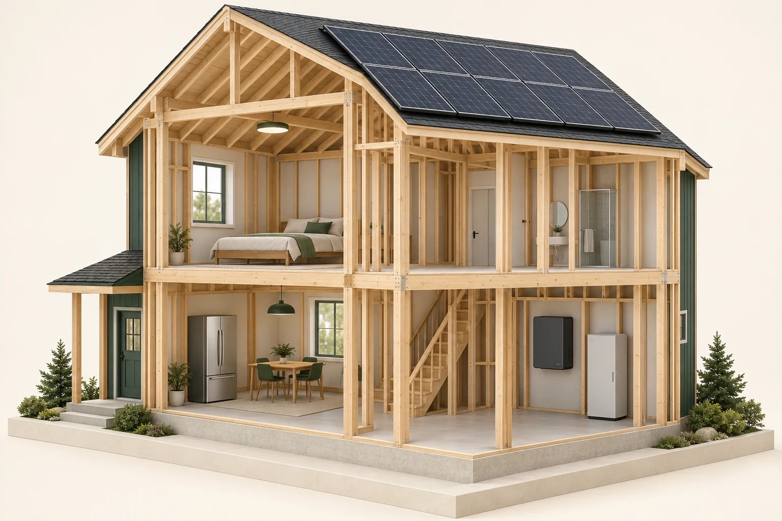
Array shapes are visible on the roof. Two closed cabinet forms and room loads appear in the open house. The model shows no complete electrical connections.
Cabinet shapes do not establish an inverter or battery identity, ownership, interconnection, transfer arrangement, capacity, backup eligibility or present condition. No wiring or approved installation is specified.
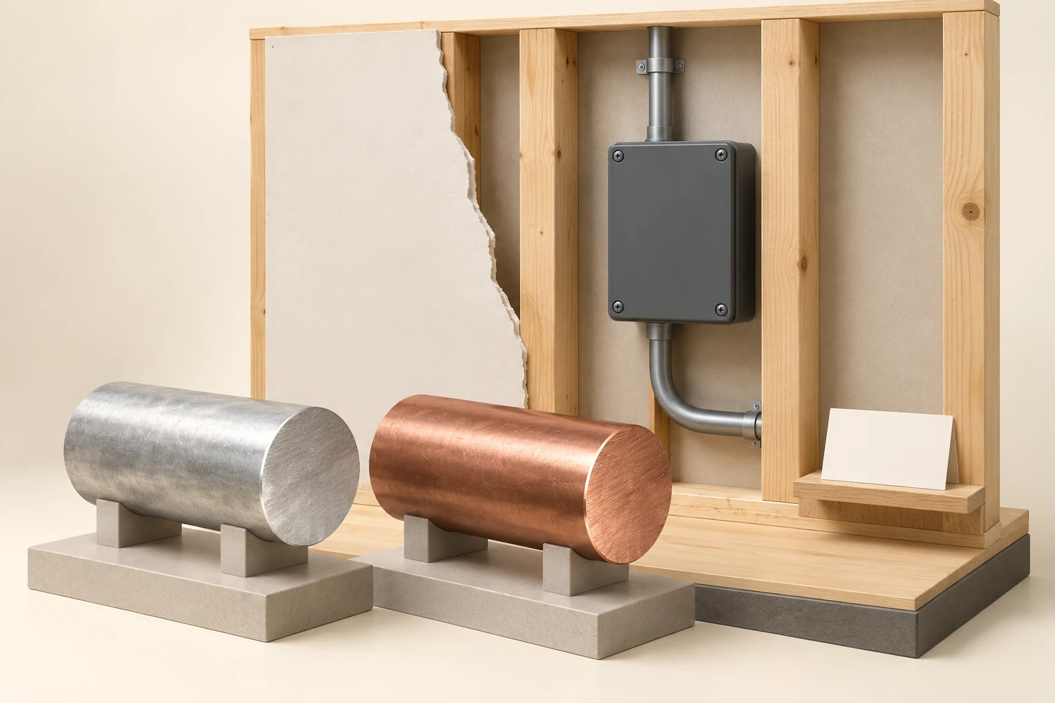
Two independent enlarged metal samples, a closed enclosure and a blank card are visible. The specimens are unconnected and do not depict live wiring.
Colour cannot identify field conductors, alloy, connector compatibility, torque, concealed work, approval or current condition. The closed enclosure shows no joints; the blank card carries no actual evidence.
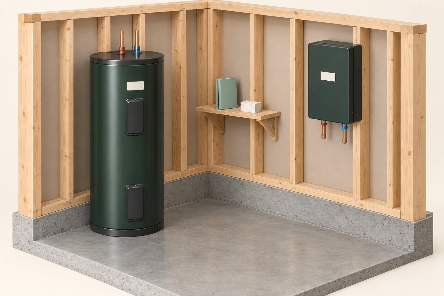
Two separate closed equipment forms and a small record shelf are visible. The short pipe stubs end at the specimen view.
Shape and colour do not identify fuel, model, capacity, temperature, approval or an installed arrangement. The units are separate specimens; concealed connections and real documents are omitted.
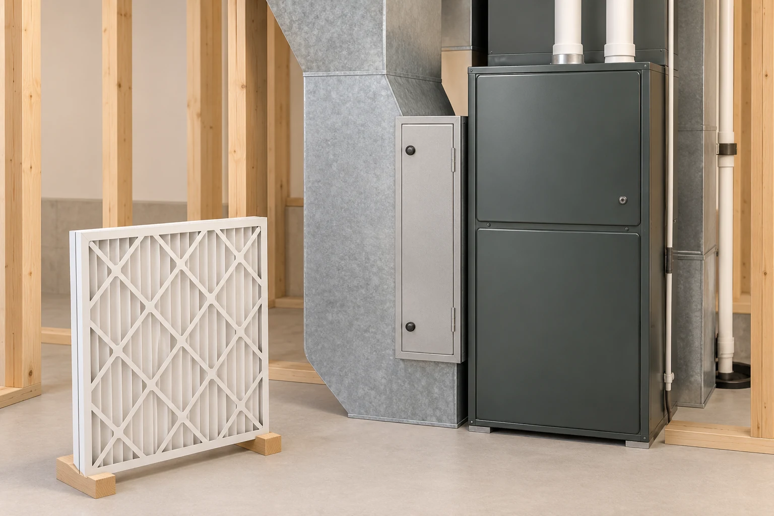
The filter sample is a freestanding teaching specimen. The nearby rack door and equipment covers remain closed.
Actual installed media, dimensions, rating, edge fit, fuel, complete routing, pressure drop, airflow and approved installation remain unknown. Visible pipes are specimens, not verified vent routes.
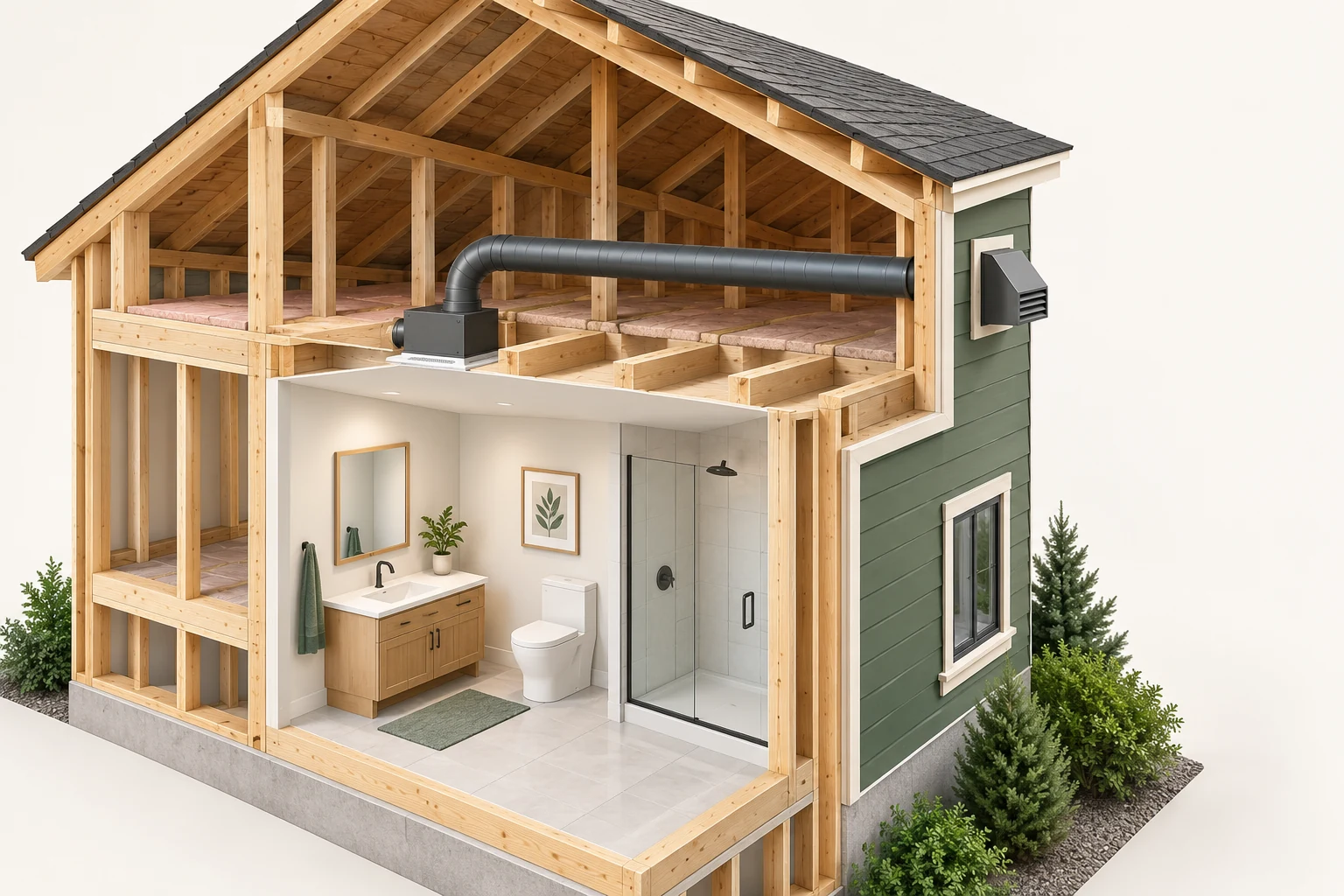
A ceiling fan housing, visible grey route and outdoor hood are separate landmarks. The scene illustrates local bathroom exhaust.
Insulation, airtightness, damper operation, concealed connections, actual airflow and an approved installation are not established.
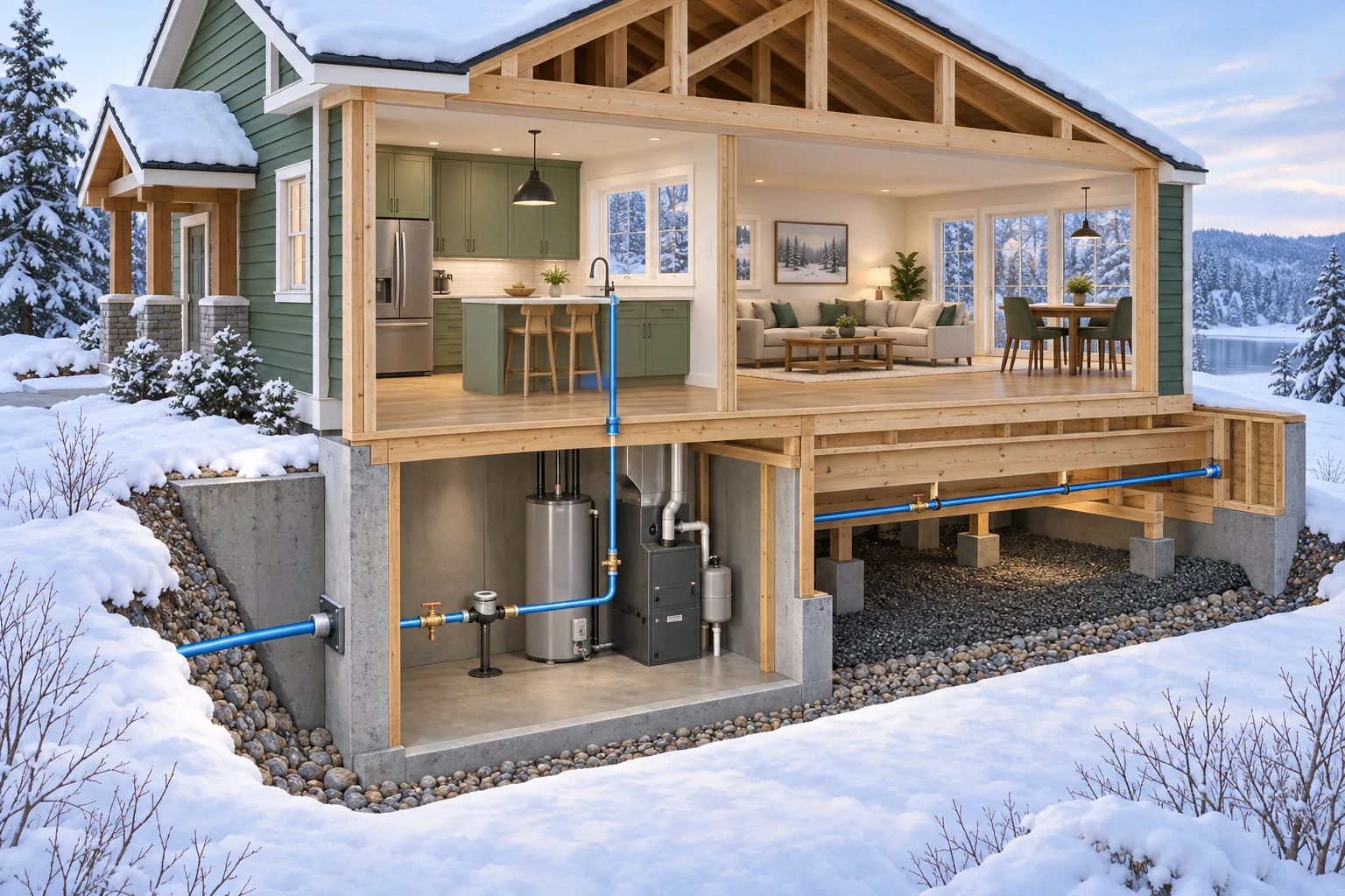
The model shows entry, utility and exposed underfloor locations. Hidden junctions remain outside the cutaway.
Colour does not identify temperature or material. Complete connectivity, buried route/depth, property boundary, actual heating and freeze protection are omitted.
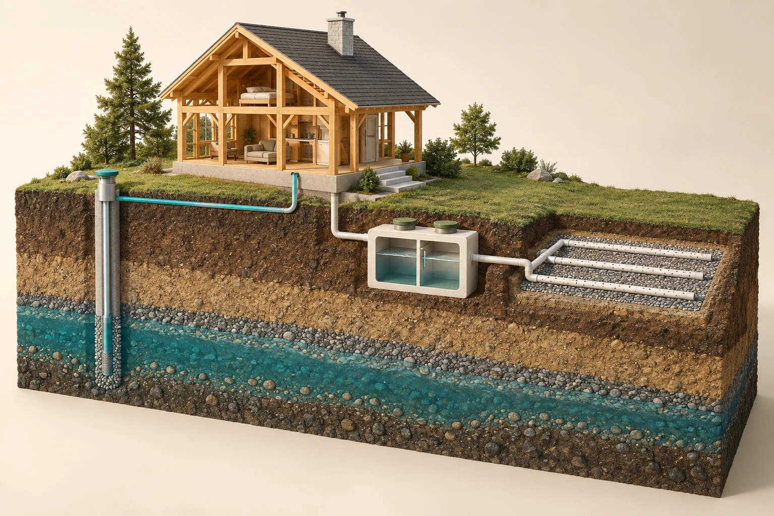
An open timber house above a soil section, with a capped well and a separate sectioned tank. A teal house-water route and a pale wastewater route toward parallel field laterals. Illustrative ground layers and a blue-green subsurface water-bearing layer.
Water quality, well construction, yield, protection and appropriate treatment. Septic inspection history, approvals, soil treatment performance and actual operation. Site boundaries, appropriate separation, groundwater conditions and local requirements.
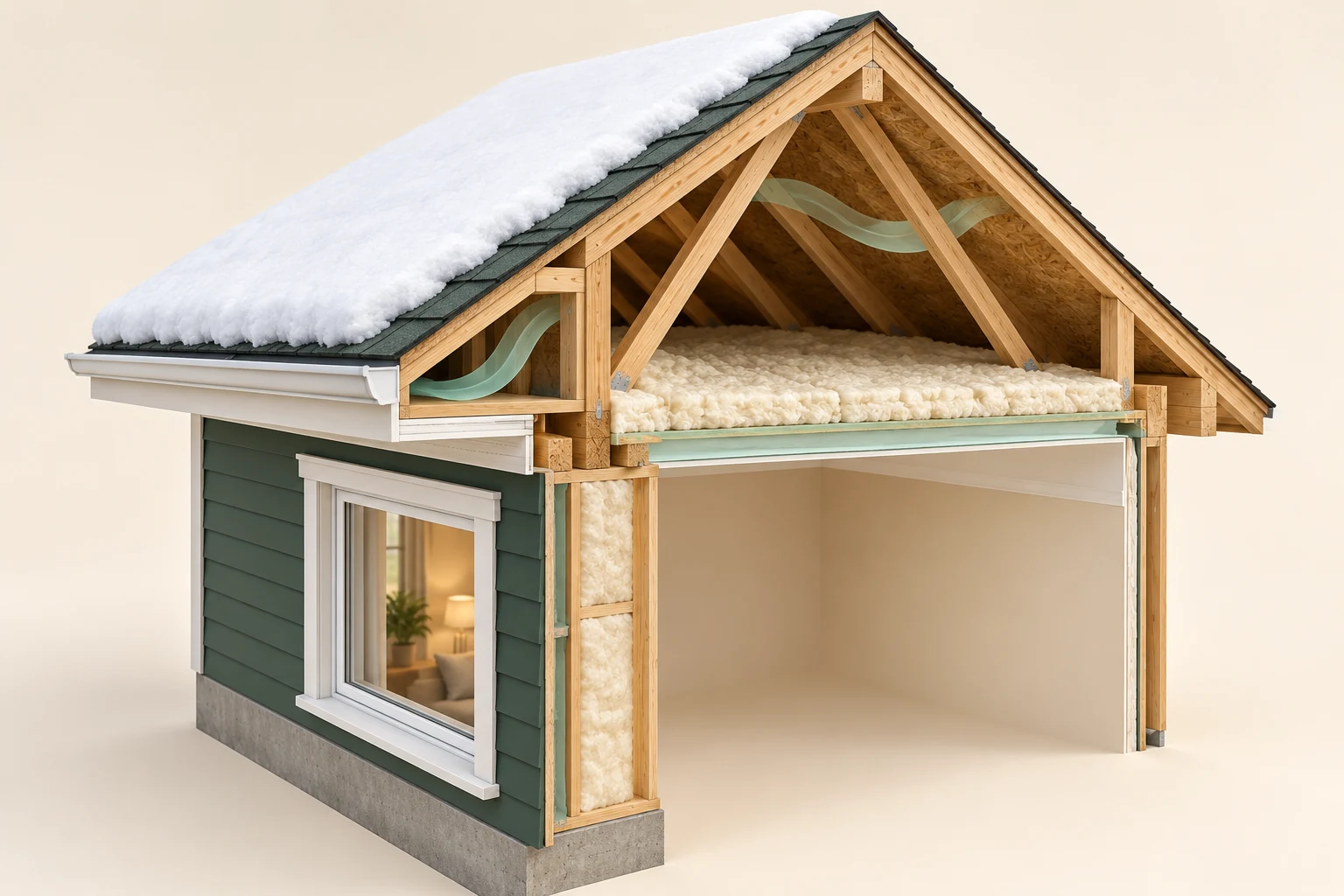
Snow over one retained roof surface, with exposed timber framing and an attic volume below. A ceiling-level insulation layer, a thin mint layer and conceptual mint air ribbons. A window and a small wall-layer section below the attic.
Snow weight, structural loading, roof capacity and the cause of any real ice or water problem. Actual air leakage, ventilation, insulation continuity and condensation conditions. The suitability of this illustrative layer arrangement for a particular building.
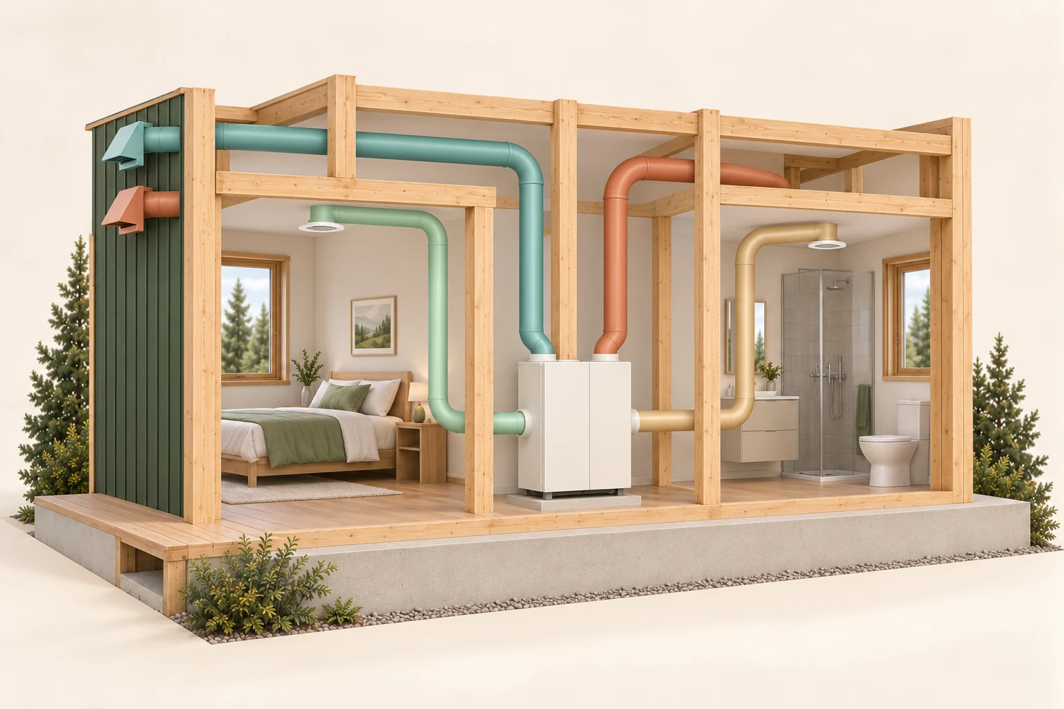
A closed ventilation cabinet with four separately coloured connections. Two outdoor hoods and two indoor grilles in an open timber-frame room model. Separate conceptual outdoor and indoor routes; part of an outdoor run passes behind framing.
The equipment type, recovery performance and manufacturer port arrangement. Commissioned airflow, balancing, controls, duct sizing and appropriate outdoor-terminal separation. Filtration performance, indoor-air exposure and the actual routing in a home.
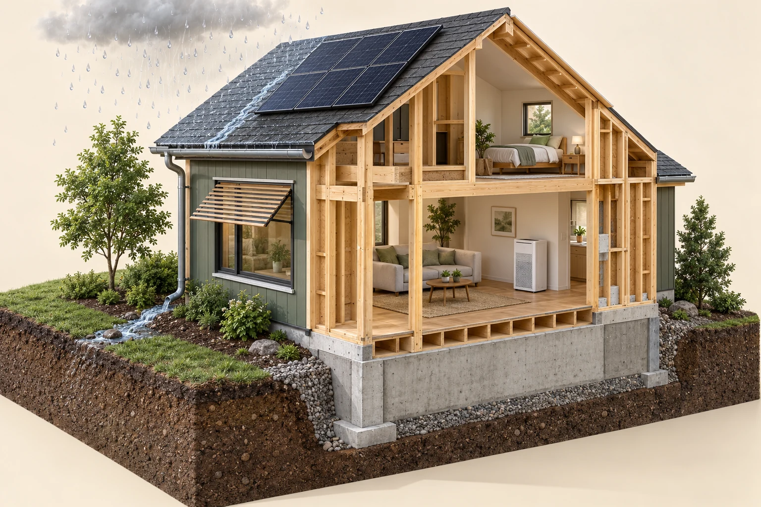
An open timber frame above a visible foundation and soil section. Illustrative rain, roof runoff, a gutter and an above-ground downspout discharge. Roof solar panels, exterior window shading and a closed indoor air-cleaner cabinet.
Actual ground slope, drainage connections, foundation moisture and flood performance. Solar output, overheating performance and suitable shading for a particular climate. Filter compatibility, achieved clean-air delivery and an appropriate site-specific design.
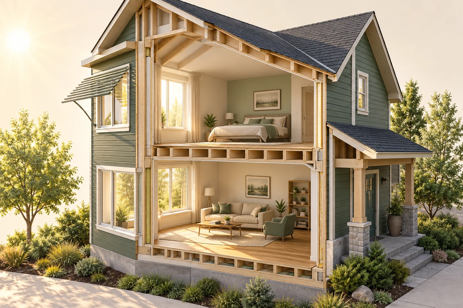
Glazing, an outside shade and room surfaces are visible. The same scene can prompt different questions about gains and stored heat.
Orientation, glass properties, actual temperatures, cooling load and health risk require separate evidence.

This paired evening illustration changes the outside light, not a measured room temperature.
A cool-looking sky does not establish cooler outdoor air, clean air, safe access or enough cooling.
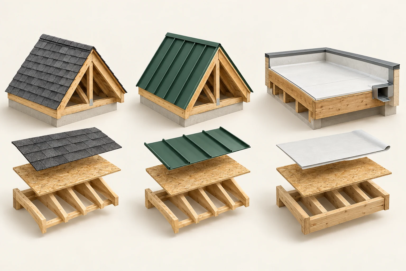
Separate coverings, decks and timber supports are pictured. The low-slope specimen also shows a side outlet.
Underlays, insulation, vapour/air control, fasteners, slope, loads and drainage capacity are deliberately not a complete design.
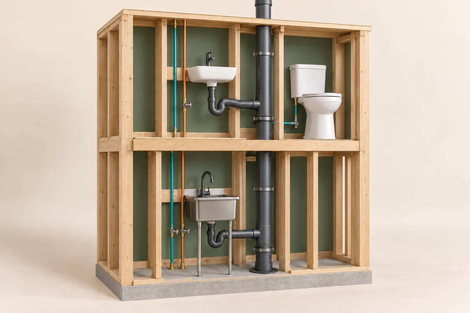
Supply pipes bring water to taps and appliances. After use, water leaves each sink through a drain and trap before joining the larger drainage route. The trap holds a water seal that limits gas passage into the room. Venting lets air circulate in the drainage system and helps protect those seals. Following these different jobs makes a repair record much clearer than calling everything plumbing.
The cutaway omits the tap connections, water inside the traps and a complete vent route to outside air. Pipe colour does not identify material. Ask a qualified plumber to explain the actual arrangement; this picture supplies no local design or approval.
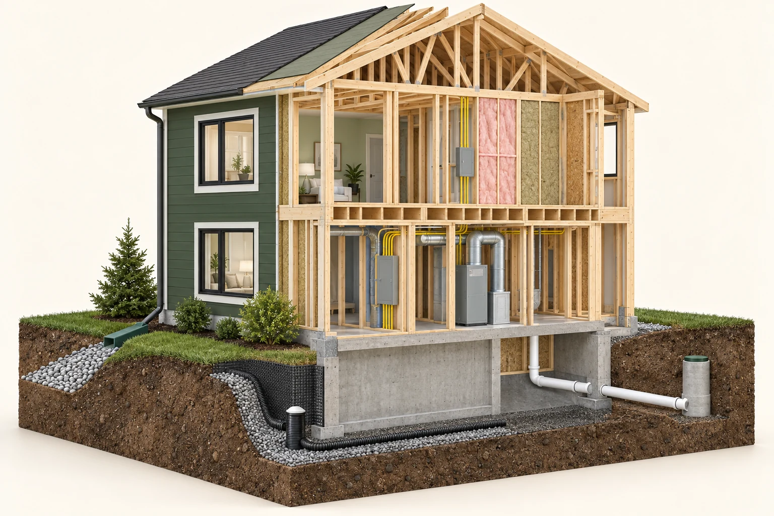
Open framing, insulation specimens, closed equipment and an illustrative buried sanitary route are exposed.
Member capacity, connections, assembly continuity, commissioned performance and pipe support are not certified by this model.
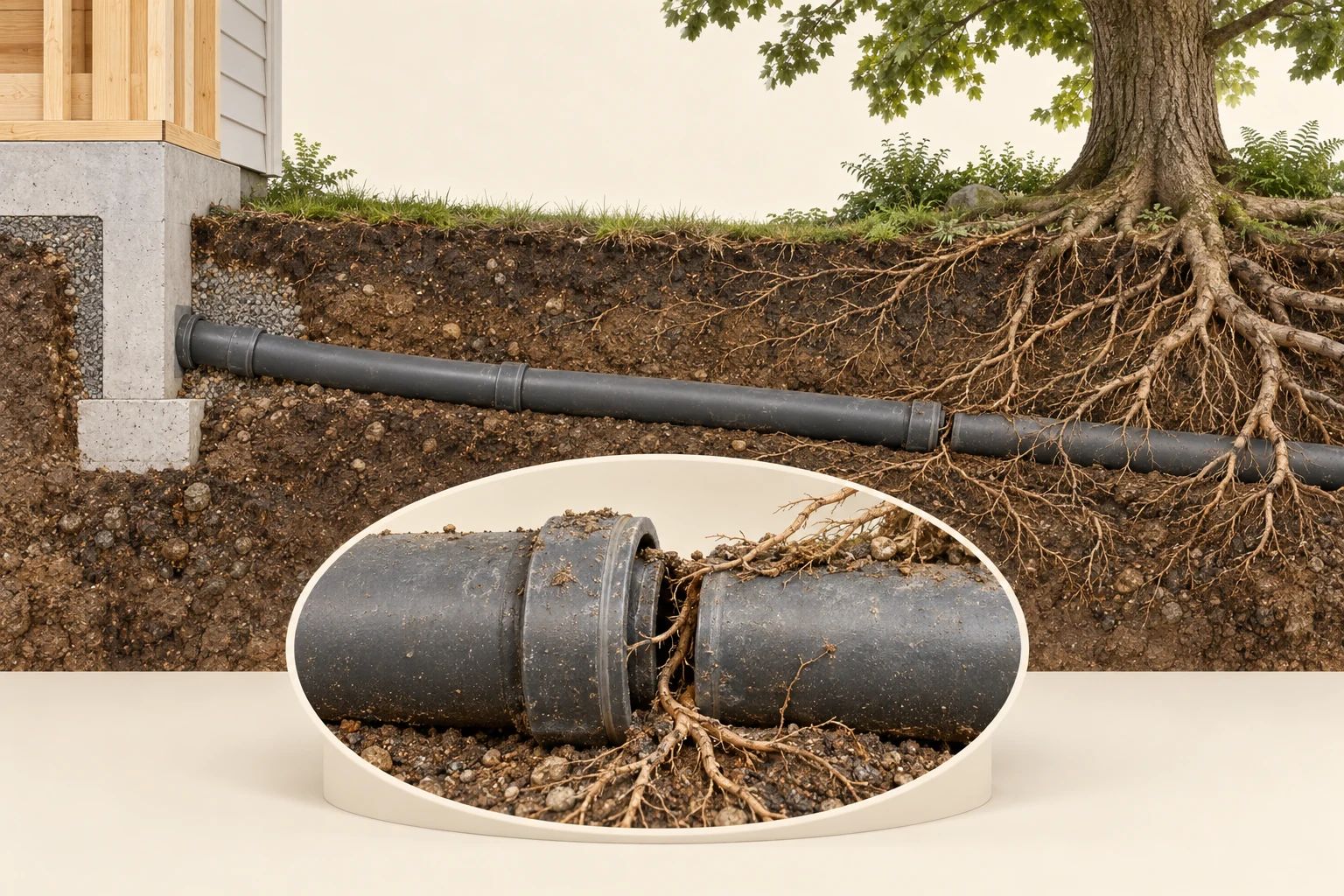
The enlarged specimen depicts fine roots at an illustrative joint opening. It is separate from the main scene and not to scale.
Material, joint condition, root presence, support, grade and responsibility at a real property need their own evidence.
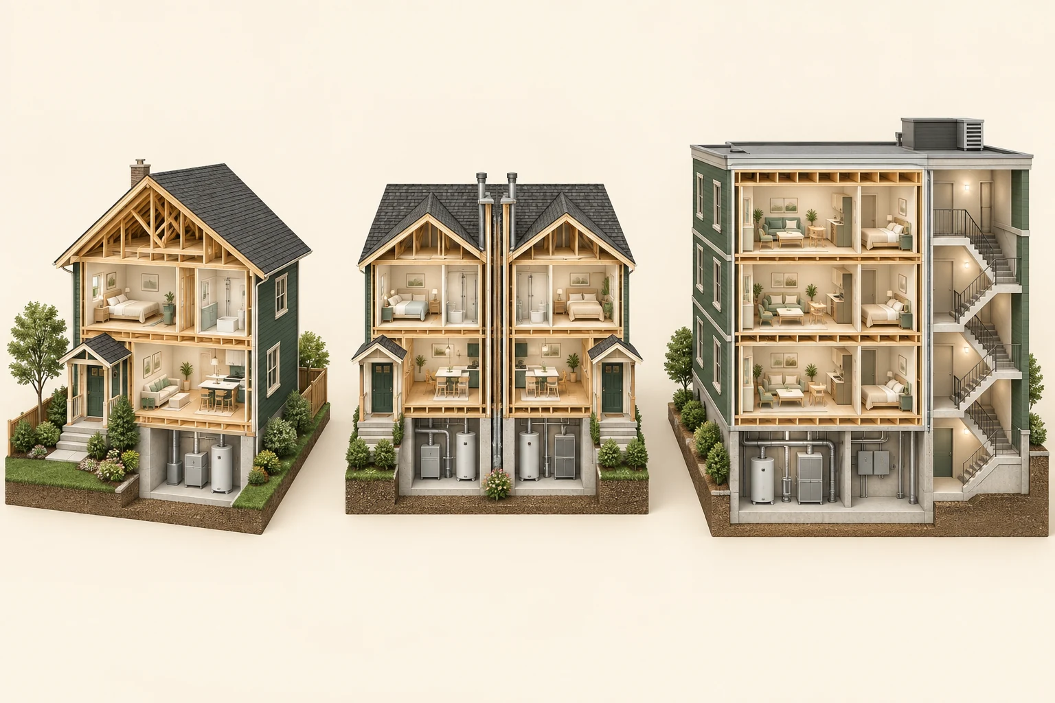
The models show different physical arrangements, shared walls and a common-equipment example.
A building shape does not establish tenure, common-property boundaries, fees, responsibility or insurance.
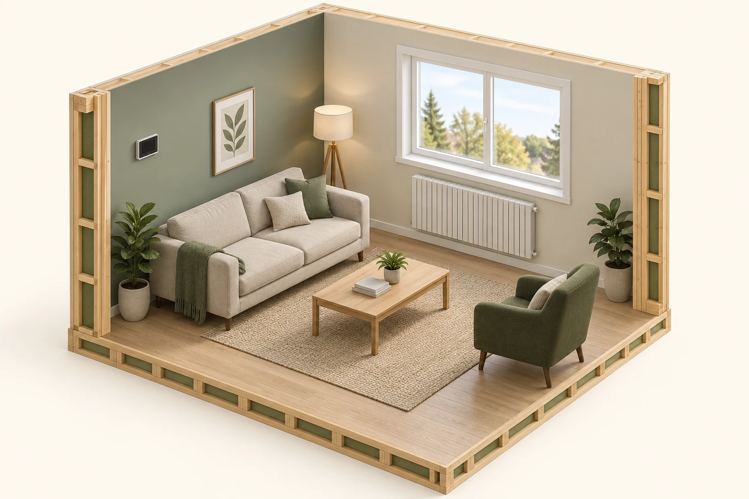
A small rectangular wall device has a blank face. A closed window, finned radiator specimen and ordinary seating appear in the room. No target, reading, heat call or measurement is displayed.
The model identifies no thermostat or sensor model, selected sensing source, fuel, wiring, control link, approved placement, room temperature, capacity, delivered heat, recovery time or energy saving. The emitter specimen has no shown connections. No settings, relocation, calibration or equipment access is suggested.
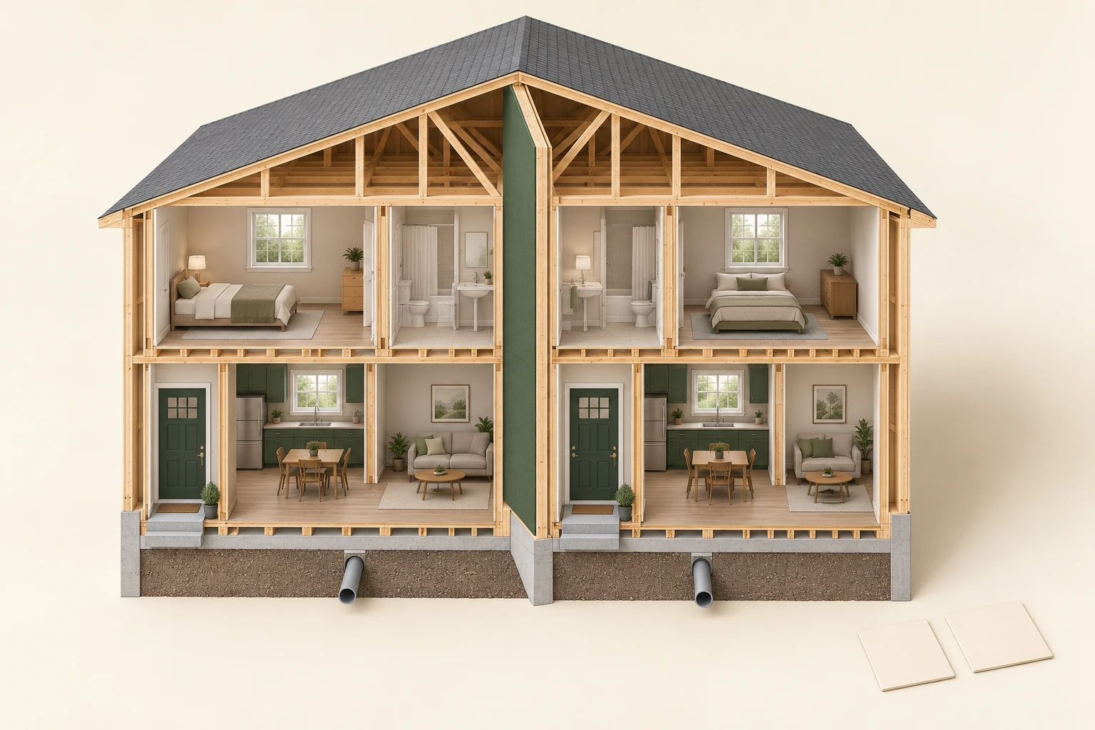
Two adjoining dwelling volumes, a continuous-looking roof, a central green separating plane and two independent terminating pipe stubs are visible. Two blank cards sit beside the model. The cutaway is a teaching specimen.
The picture establishes no tenure, title boundary, common property, actual assemblies, structural capacity, fire or acoustic rating, approved detail, complete pipe route or municipal connection. Roof appearance and stub position assign no ownership, authorization, access right, maintenance duty or cost. Colours identify illustrated features only.
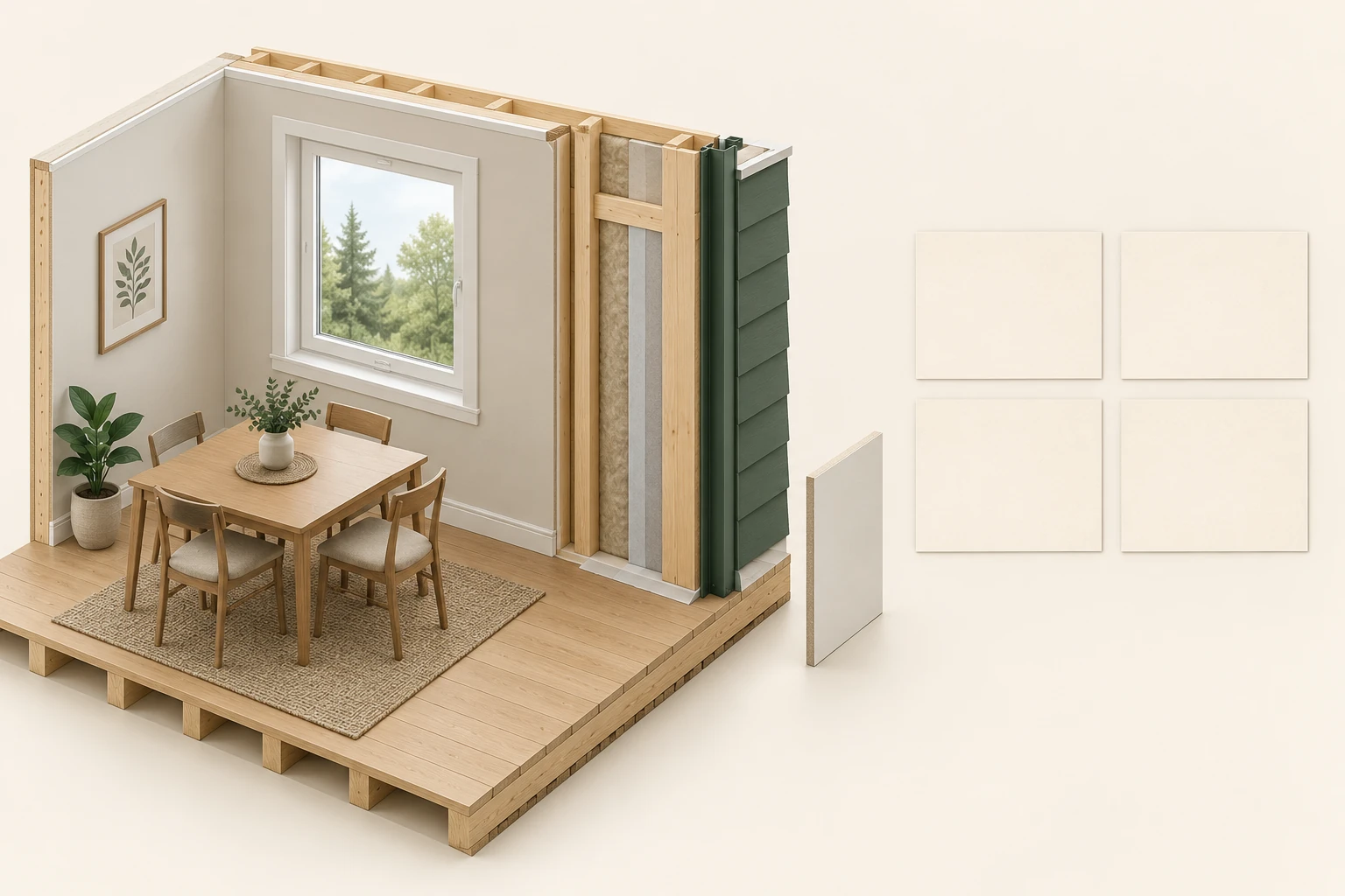
A closed window, dining area and layered wall edge appear beside a green exterior corner strip. A detached finish sample and four separate blank cards sit outside the room specimen. No damage, moisture, dates or real documents are shown.
The model proves no reported event, completed repair, material specification, actual leak route, causation, concealment, structural finding, disclosure duty, successful result or lasting dryness. The layers are conceptual and are not a removal or repair instruction. Blank cards provide no chronology or actual evidence.
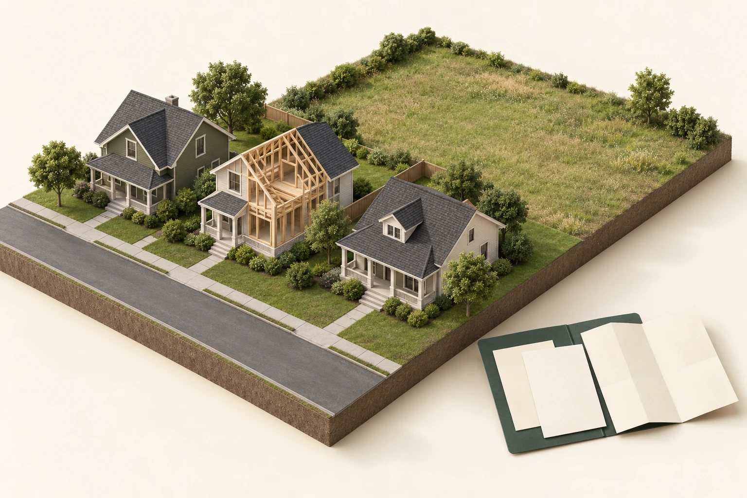
Three house forms face a street. One has an illustrative skeleton cutaway. An open grassed area, trees and fences appear behind the homes. A separate folder contains blank sheets and a folded blank sheet.
The scene establishes no surveyed parcel, title boundary, land-use designation, planning application, decision, conditions, permit, approved building, infrastructure, construction timing, shadow result or future value. Fences and ground texture are not a survey or grading result. The grassed area has no supplied development proposal, and the cutaway identifies no real work in progress.
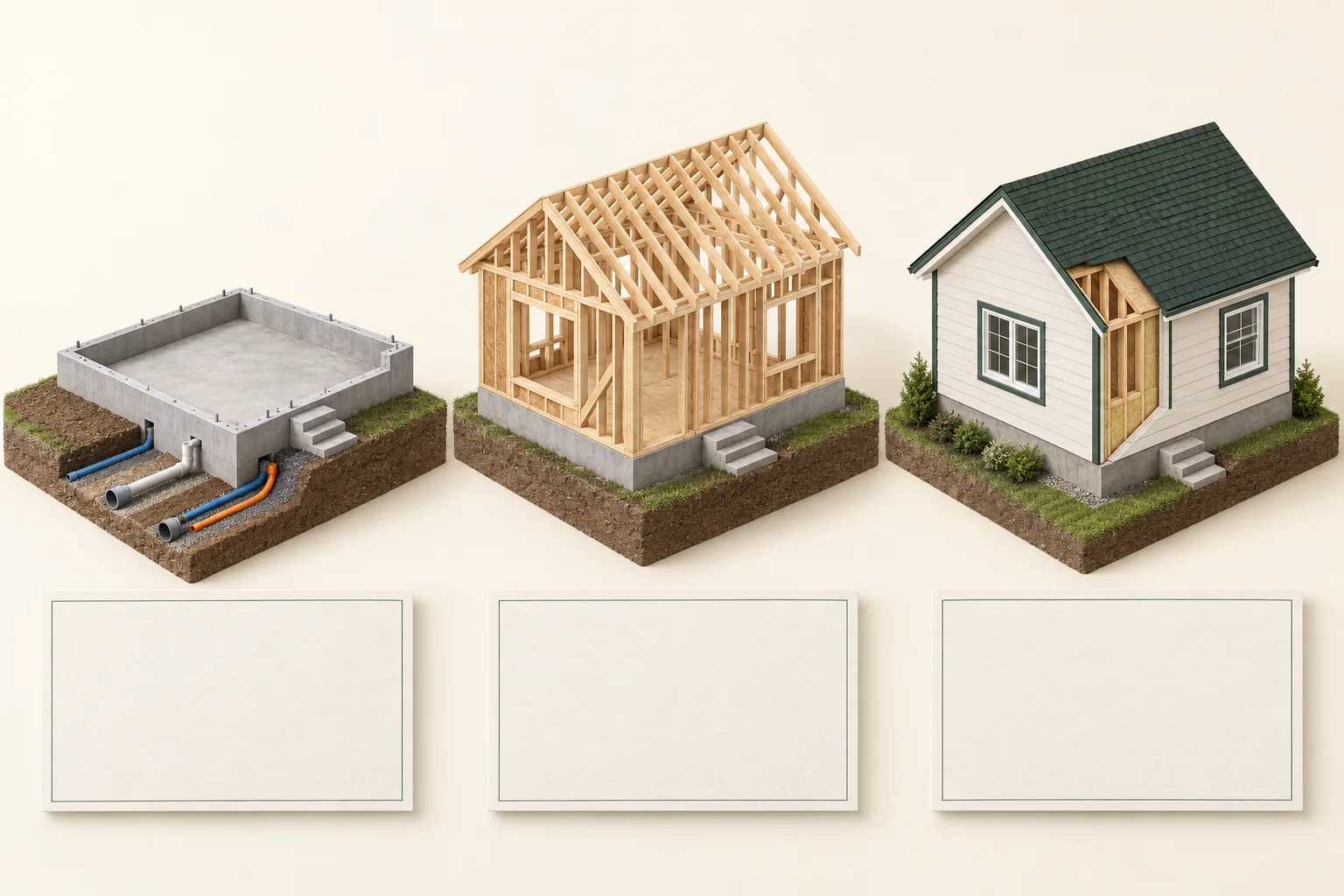
Three educational house specimens stand above blank cards: a concrete foundation with short open coloured service segments, exposed timber framing, and a roofed and clad house with an intentionally open wall strip. They illustrate changing visibility as work progresses.
The specimens do not establish one property’s verified construction sequence, dates, inspected scope, approvals, structural adequacy, concealed connections, commissioning or completed corrections. Pipe colours and short visible openings do not identify service function, endpoints, routing, condition or a connection to the city. The blank cards contain no actual construction record. Match dated and located records to the real component and explain later changes.
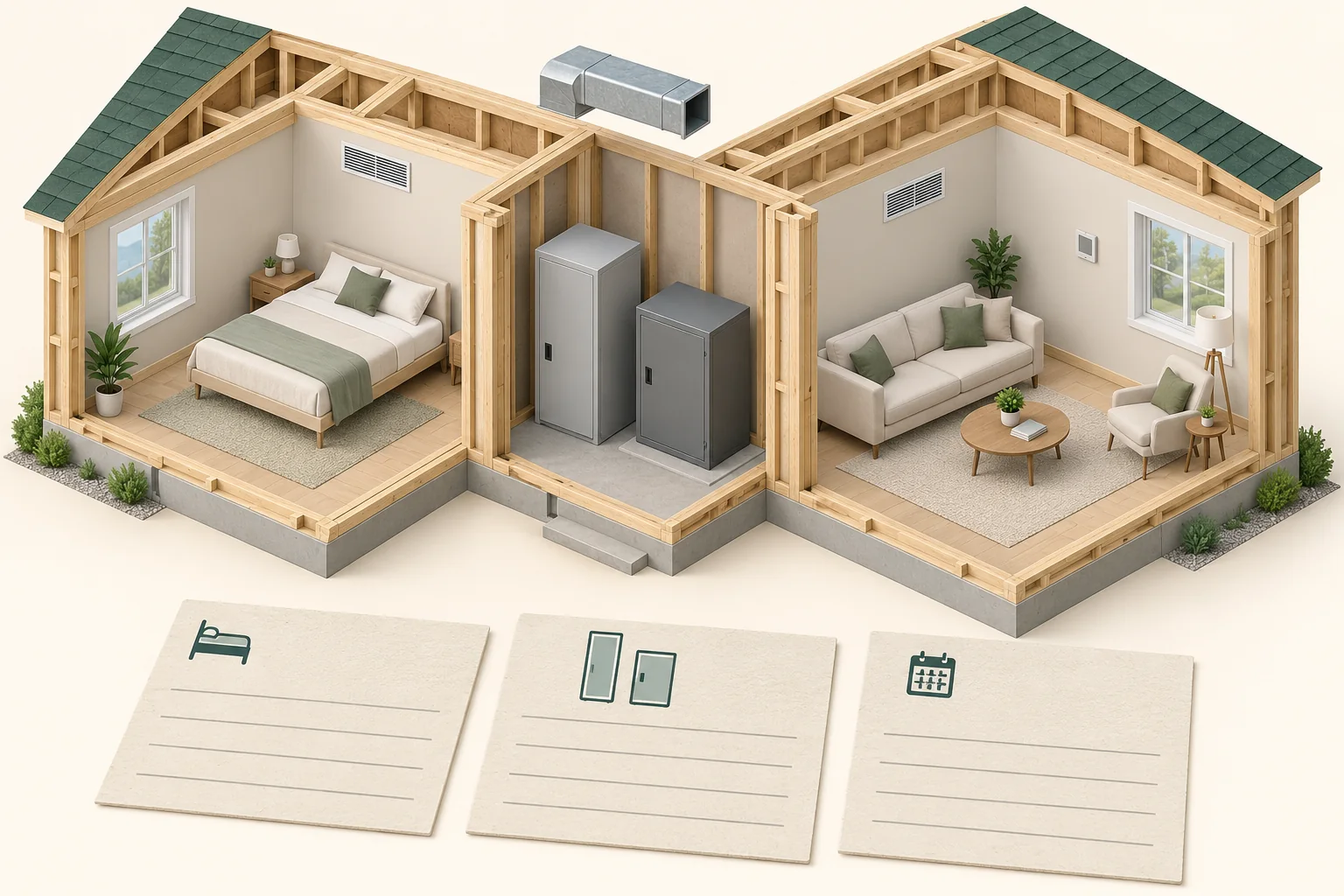
A timber cutaway bedroom and living room each contain a wall grille and flank two closed grey cabinets. A detached grey duct sample sits above them. Three cream cards show bed, paired-cabinet and calendar pictograms above blank lines; they are illustrative record placeholders.
The picture identifies no equipment model, serial number, installed purpose, duct connection, flow direction, delivered airflow, room pressure, control setting, capacity or commissioning result. The cabinets are closed, and the detached duct sample establishes no continuous installed route. The pictograms and blank lines contain no actual room record, equipment entry, test reading, date or completed follow-up. Actual configuration and measured findings must be matched to the home and retained with later changes.
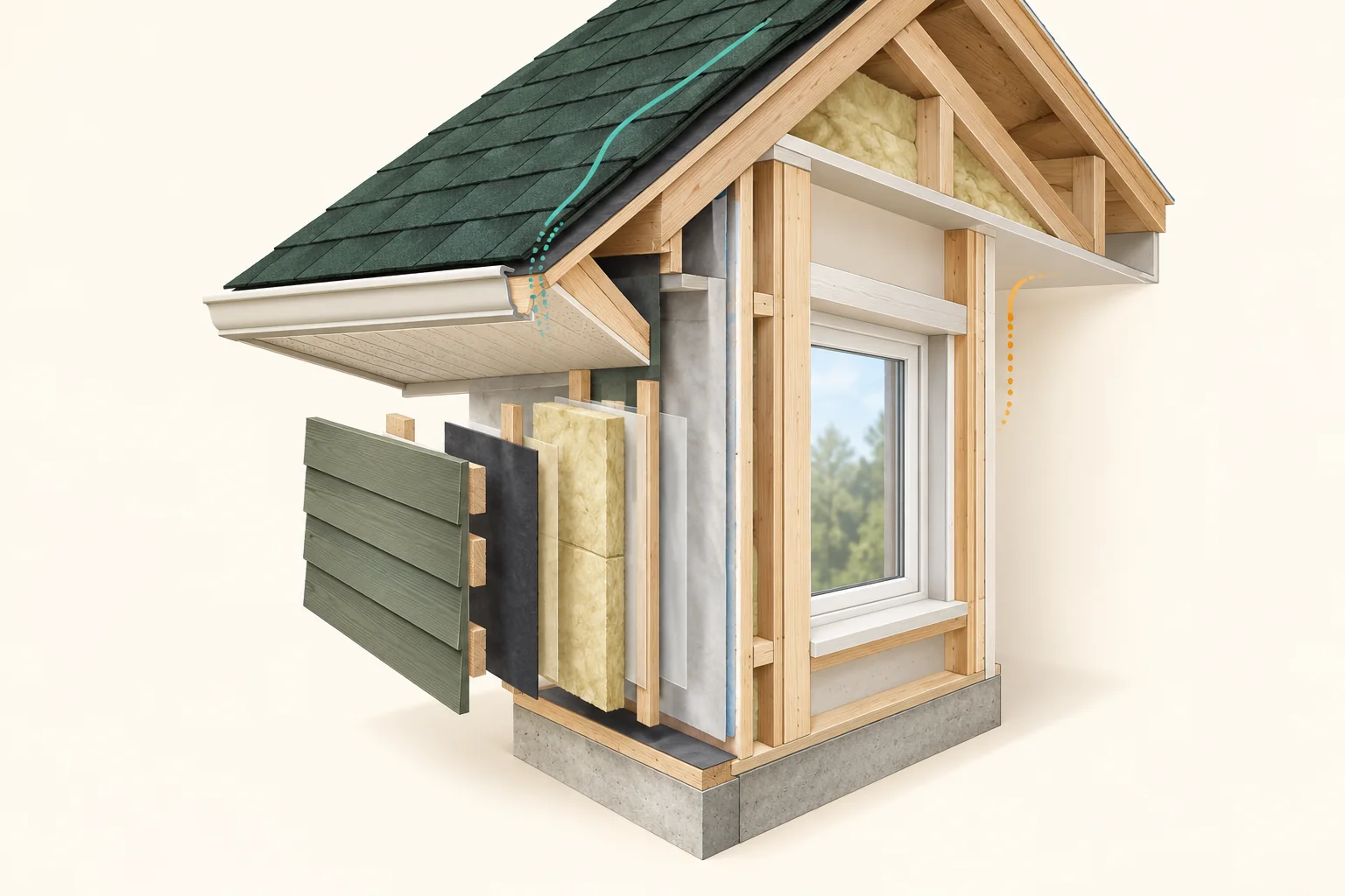
An educational roof, wall and window corner shows dark shingles and an eave, timber members, pale infill and a separated finish/material sample beside a closed glazed opening. Teal and amber traces end or fade around the roof edge and room side; they are prompts for separate functional questions.
The separated sample does not establish an installed layer order, approved assembly, attachment detail, air or rain-control continuity, drying capacity, ventilation or measured thermal performance. The coloured traces are illustrative prompts, not water paths, pressure measurements, leak findings or installation instructions. The cropped roof shows only part of the specimen. An actual junction needs matched detail records and an assessment scoped to the specific concern.
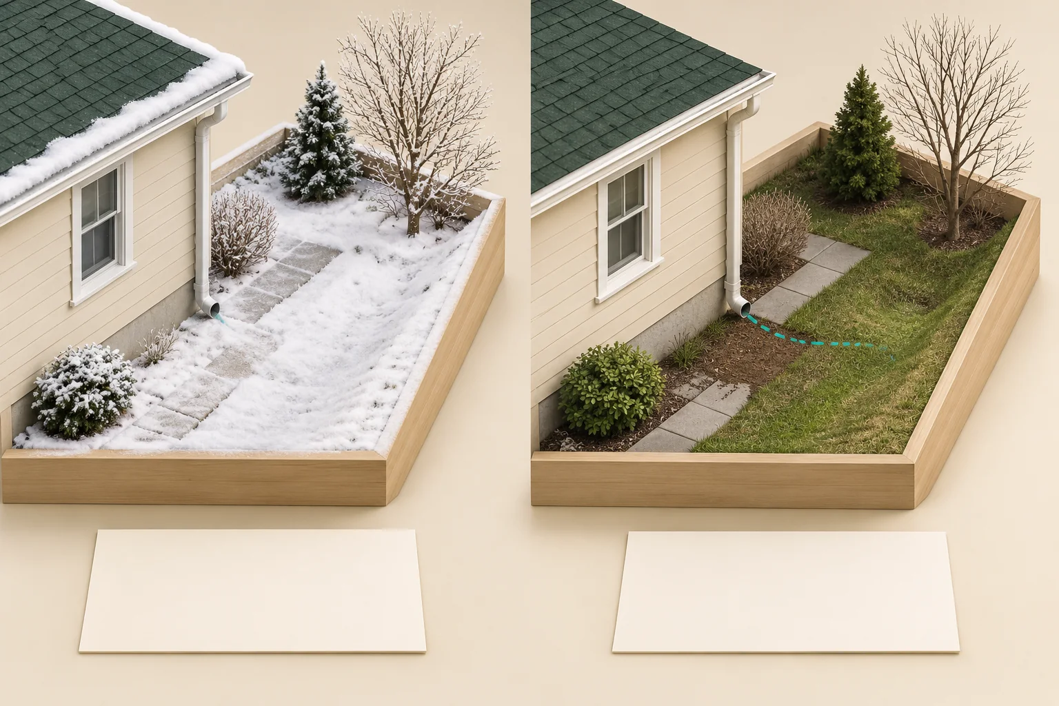
Two educational seasonal views show house corners, windows, downspouts, paving and landscaping. Snow covers much of the left sample; the right sample is snow free. A teal dashed trace starts beside the right downspout and fades over soil and lawn. Empty cards and timber display edges accompany the views.
The two specimens do not establish one property’s dated before-and-after condition, completed grading, surveyed levels, actual water movement, buried routes, rainfall response or approved discharge destination. The teal dashed trace fades without identifying an endpoint. The timber edge is a model display edge, not a property boundary or evidence of a retaining installation. No card documents a completed obligation, inspection or deadline. A later assessment must name its actual conditions, scope and remaining limits.
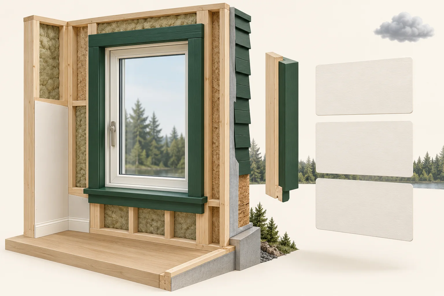
A closed white-framed window, visible handle and dark green trim sit within an exposed timber and pale-infill wall specimen. A separate timber-and-trim sample stands beside three blank cards. The small cloud above the cards is a weather prompt.
The closed, dry-looking specimen does not demonstrate successful operation, air or water tightness, rain-linked behaviour, approved flashing, installed barrier continuity, an actual defect, completed repair or verified closeout. The cloud is a symbol rather than observed weather. The separated sample establishes no installed detail, and the blank cards contain no dates, attributed work, inspection findings or warranty submission. Keep actual located observations, the described work and the specific follow-up scope as distinct linked entries.
Connect a guide's mechanism with what you observed, the documents available and the assessment still needed. HAUSE-trained realtors can help coordinate that conversation with the relevant specialists, subject to confirmed training, credentials and availability.